

Content last revised on September 21, 2026
Preventing Spurious Faults: Turn-On Current Rise Limiting for DD160F120
Before energizing a replacement, isolate the soft starter, inspect the PowerBlock body and terminals, then verify the nameplate boundary of 1200 V and 160 A against the original installation record.
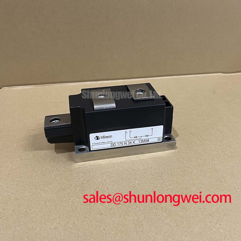
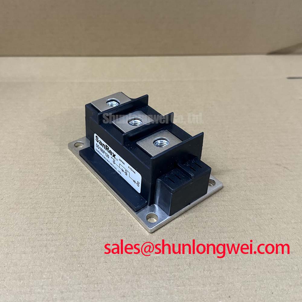
The Infineon DD160F120 is a PowerBlock Module classified here as a diode module. Its confirmed factory parameters are a 1200.0 V specified voltage rating and a 160.0 A specified current rating. These values identify the device class, but they do not by themselves confirm suitability for every motor starter duty cycle. The system engineer should also verify the circuit topology, cooling arrangement, repetitive current profile, surge conditions, fuse coordination, and terminal layout before installation.
| Manufacturer | Infineon |
| Model | DD160F120 |
| Product category | Diode Module |
| Package | PowerBlock Module |
| Specified voltage rating | 1200.0 V |
| Specified current rating | 160.0 A |
In a high voltage three phase motor solid state soft starter, the DD160F120 should be evaluated as part of the complete power path rather than as an isolated replacement. Confirm which terminals belong to the diode conduction path by comparing the original wiring diagram, enclosure markings, and service documentation. Do not infer terminal polarity from physical position alone. A replacement with the correct voltage and current class can still be unsuitable if the phase arrangement, heat transfer path, or protective coordination differs from the original assembly.
RC snubber networks and series saturable reactors are system level measures used to control switching transients and current rise. Their values must be selected from the measured commutation behavior, wiring inductance, load characteristics, and the actual switching devices in the starter. The supplied factory data confirms the DD160F120 voltage and current ratings, but no snubber value, reactor value, or maximum allowable rate of change should be invented from those two ratings. Designers should validate transient voltage and current with an appropriately rated measurement setup during controlled testing.
A diode module does not provide a gate input. If the soft starter uses phase angle control through separate thyristors, the firing pulse, firing delay, gate current, gate voltage, dead time, and short circuit response belong to the thyristor control assembly. They should not be attributed to the DD160F120. This distinction is important when diagnosing a starter that shows irregular conduction, incomplete commutation, or phase imbalance.
When checking a suspected unit on the bench, begin with power removed and all capacitive energy discharged according to the equipment service procedure. Record the terminal arrangement before disconnecting conductors. Inspect for cracked insulation, loose clamping surfaces, discoloration, damaged threads, and signs of uneven thermal contact. A multimeter resistance check may help identify an obvious open or short condition, but it cannot prove blocking performance at the rated voltage. Any insulation or blocking test must follow the module documentation and the host equipment safety procedure.
Fuse coordination requires the manufacturer’s published I²t information for the complete protection scheme. The confirmed product information supplied for this page does not include a fuse I²t value, a repetitive overload curve, or a non repetitive surge current rating. Selective protection therefore remains a system engineering task. Engineers evaluating related power paths may also review the DDB6U180N16RRP_B37 as a separate front end or auxiliary stage reference, without treating it as an automatic substitute for the DD160F120.
Field Alert: Follow the original hardware specification for mounting pressure and terminal tightening, and never reconnect power conductors while the soft starter remains energized.
Benchtop Waveform Tuning: Mitigating Stress via Dynamic Firing Delay Angle Adjustment on DD160F120
When a three phase soft starter uses controlled thyristors, changing the firing delay angle changes the portion of each AC half cycle delivered to the motor. The resulting voltage, current, power factor, reactive demand, and heating must be observed at the complete assembly level. The DD160F120 is a diode module, so it should not be described as the device that generates or adjusts a firing angle. Its role depends on the rectifier or auxiliary conversion section in which the system integrator installs it.
For a bench evaluation, compare all three phases under the same test conditions. Record line voltage, phase current, conduction timing, DC link behavior where applicable, and the temperature trend at the module mounting surface. An oscilloscope with suitable differential probes can help reveal commutation spikes or unexpected conduction overlap. Current transformers or isolated current probes should be selected for the expected waveform and bandwidth. A visual waveform alone is not enough to approve a high voltage replacement.
Control engineers should verify that the external firing circuit does not impose an unintended conduction path through the diode assembly. Gate trigger characteristics such as IGT and VGT apply to a compatible thyristor, not to the DD160F120 diode module. A pulse train that is appropriate for a separate SCR assembly cannot be used as evidence that this diode module has been correctly driven. The correct evaluation is to trace the power topology and confirm how each semiconductor contributes to the positive and negative current paths.
Where the rectifier section supports a battery backed DC link or bidirectional DC to DC subsystem, thermal cycling should be assessed under the actual charge and discharge profile. The module’s confirmed 1200 V and 160 A ratings do not establish a battery cycle life, switching frequency limit, or cooling requirement. Those conditions are determined by the complete converter, its bus voltage, load profile, heatsink, airflow, and protection strategy.
Bootstrap capacitors and common mode ground bounce belong to the associated gate driver and switching topology. Diode reverse recovery is a semiconductor characteristic that must be evaluated within the associated switching topology. These factors should be checked separately when the starter includes insulated gate devices or controlled thyristors. Avoid assigning a driver supply voltage, negative gate bias, dead time, or desaturation response to the DD160F120 unless those values are explicitly stated for the actual control assembly. For broader application context, the Industrial Applications reference can support system level review, while the individual module ratings remain the controlling product facts.
The SanRex Sansha Electric Power Semiconductor Modules resource provides useful industry context on power semiconductor module application and handling. It should not be treated as a substitute for the Infineon documentation applicable to this exact model.
DD160F120 Operational Boundaries: Evaluating Mechanical Torque Shock Elimination in Heavy Duty Systems
A soft starter can reduce mechanical shock when its control system manages motor acceleration progressively, but the DD160F120 itself does not establish a guaranteed motor inrush reduction or a fixed torque profile. Claims such as reducing locked rotor current from a particular multiple to a specific target require motor data, starter topology, firing control, load inertia, supply impedance, and commissioning measurements. These values should be treated as system results, not as factory specifications for the diode module.
During commissioning, compare the motor manufacturer’s rated current with the measured current at initial energization, acceleration, and bypass transfer. Watch for phase imbalance, unexpected current peaks, unstable control transitions, and temperature rise at the power module. A current waveform that appears acceptable at light load may change substantially when the driven machine reaches its actual mechanical load. The engineer should verify peak electrical stress against the supply and insulation limits of the complete starter.
Mechanical installation deserves the same attention as electrical matching. The base must be clean and flat, the thermal interface must be applied according to the module and heatsink instructions, and the clamping arrangement must distribute pressure evenly. Do not compensate for a poor heatsink interface by increasing bolt force. Excessive pressure can distort the mounting surface or damage the package, while insufficient pressure can increase thermal resistance.
For a field replacement, photograph the original conductor routing and identify each phase before removal. Check whether busbars, flexible links, insulating barriers, and creepage distances can be reinstalled without mechanical strain on the module terminals. The PowerBlock form factor is a package description, not a universal guarantee of dimensional interchangeability. Confirm the hole pattern, terminal spacing, insulation clearances, and heatsink contact area from the applicable mechanical drawing.
A neutral reference model such as TD210N12 may be reviewed during a broader selection study, but a different current or voltage designation does not make it an automatic replacement. Engineers should compare the full electrical, mechanical, thermal, and protection data before approving any alternative device.
DD160F120 Circuit Protection and Reliability: Calibrating Non Repetitive Surge On State Current
Short duration surge current is a protection coordination issue that must be checked against the actual semiconductor data and fault clearing system. The confirmed information for the DD160F120 identifies 1200.0 V, 160.0 A, and the PowerBlock Module package, but it does not provide an official ITSM value, 10 ms half cycle surge curve, junction temperature limit, thermal impedance, or fuse I²t coordination table. Those parameters must be obtained from the applicable manufacturer documentation before a surge withstand claim is made.
In a controlled protection review, first identify the prospective fault current, supply impedance, fuse type, clearing behavior, and fault duration. Then compare those conditions with the module’s official repetitive and non repetitive ratings. The junction temperature should be evaluated from the real heatsink, interface condition, ambient environment, current waveform, and duty cycle. A single cold resistance measurement cannot validate surge capability or prove that reverse voltage may safely be reapplied.
After a protective operation, inspect the module, fuse, busbars, insulation system, and neighboring components before re energizing. A fuse that has opened may indicate an external fault, a transient event, incorrect coordination, or semiconductor damage. Determine the failure condition through measured evidence rather than assigning one cause from the visible symptom. Verify blocking behavior and insulation condition using an approved test method, then compare the findings with a known good phase path where appropriate.
Thermal cycling in battery charging equipment, rectifier sections, and motor control panels should be reviewed as a complete system reliability question. No field life figure, failure rate, or guaranteed operating hour claim is established here for the DD160F120. Engineers should use the current manufacturer documentation, measured thermal data, and the equipment duty profile when deciding whether the existing cooling and protection arrangement remains suitable.
Before releasing the repaired soft starter, confirm conductor identity, insulation clearance, mechanical seating, protective device coordination, and the measured phase waveforms under controlled load. The final acceptance decision belongs to the responsible system engineer and should be based on the verified installation conditions rather than the module ratings alone.