




Content last revised on September 30, 2026
Field Diagnostics and Commissioning: Rectification in DFA150BA80 Circuits
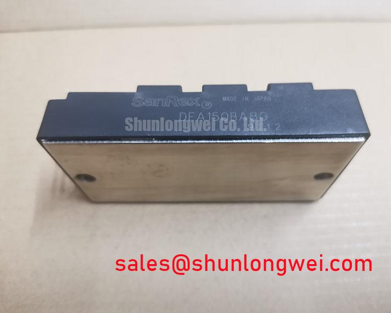
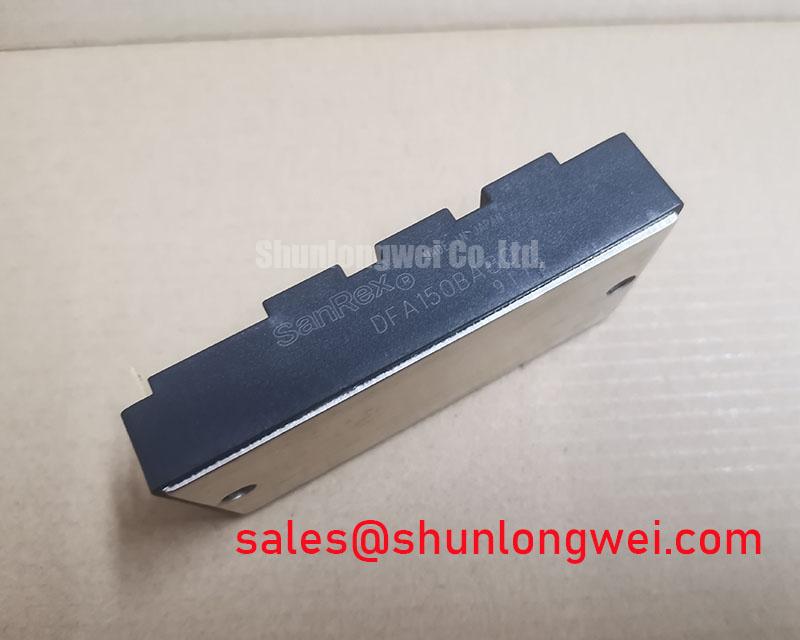
DFA150BA80 | Manufacturer: SanRex (Sansha Electric) | Category: Bridge Rectifier Module | Enclosure: SanRex Power Module | Published voltage and current values: not supplied in the provided factory specifications.
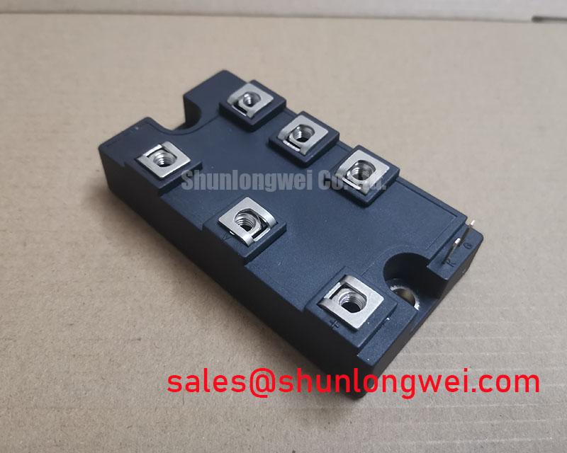
Measure the isolated module’s main-terminal paths and compare their polarity with the equipment schematic before reconnecting DFA150BA80. Record any unexpected open or low-impedance path, then check the connected bus and wiring separately so an external fault is not attributed to the module. The supplied product information identifies a bridge rectifier module but does not provide its terminal diagram or numerical voltage and current ratings; obtain the applicable SanRex drawing to identify each connection and its limits.
Firing-angle checks belong only to a circuit whose schematic and device documentation establish controlled rectification. Do not assume this bridge module has thyristor gate terminals. If the equipment uses a separate phase-controlled stage, compare its gate timing, input current and DC output waveforms under the same load conditions. A change in firing angle can affect input power factor and reactive-power demand, but a single voltage reading cannot establish the cause of a commissioning fault. The Vienna rectifier topology illustrates a different approach to three-phase rectification; its control behaviour should not be applied to this module without circuit evidence.
Benchtop Waveform Tuning: Commutation Stress in DFA150BA80
Probe the voltage across the rectifying path during commutation and compare the peak with the incoming AC and DC-bus waveforms. Repeat the measurement at the operating conditions relevant to the reported fault. Ringing may involve wiring inductance, the surrounding snubber or the load; its presence alone does not identify a failed junction.
Reverse-recovery peak current and recovery time can influence commutation stress, but no values for either parameter are present in the supplied specifications. Do not assign recovery behaviour or switching-loss figures to DFA150BA80 from a different module’s curves. As a Design Consideration, keep the measured current loop compact to limit inductive voltage overshoot, and let switching tests establish the resulting voltage margin for the actual installation. 🔧 Bench Diagnostic: Isolate and discharge the equipment before moving probes between power terminals.
If the surrounding circuit includes a controlled switch, review its drive waveform independently rather than treating this rectifier as an IGBT. Precision Gate Drive Design is relevant to that separate drive circuit; gate-drive settings cannot be inferred from the DFA150BA80 designation.
Benchtop Waveform Tuning: AC Input Transient Protection
Capture the AC-terminal voltage during the reported transient and inspect the existing surge-protection path for loose connections or visible damage. Compare measurements at the equipment input and at the module terminals: a clamp upstream may operate without holding every downstream node to the same peak voltage.
As a Design Consideration, coordinate any metal-oxide varistor and RC snubber with the equipment’s source impedance, grounding arrangement and measured transient waveform. Confirm the module’s documented repetitive and nonrepetitive voltage limits before selecting clamp components; the supplied specifications contain no numerical limits from which to size them. Surge testing is a system-level exercise, not an approval carried by an individual rectifier module. For a grid-tied static var compensator or thyristor-switched capacitor assembly, verify the actual rectifier function and protection schematic before treating this part as a compatible service unit.
Preventing Spurious Faults: Semiconductor Fuse Selection for DFA150BA80
Read the installed fuse markings and compare its location with the short-circuit path on the equipment schematic. A fuse that repeatedly opens calls for checks of the bus, connected load and rectifier paths; replacing it with a different rating before locating the fault can obscure the evidence.
Fuse coordination requires the candidate fuse’s total clearing I²t under the available fault conditions and the module’s documented surge-current and I²t withstand limits. Those module limits, a fuse coordination table and terminal tightening torque are not supplied here, so no protective match or damage-free short-circuit outcome can be claimed. As a Design Consideration, verify prospective fault current, fuse interrupting capability and thermal conditions against the completed assembly’s documentation. Mounting hardware and thermal-interface application should likewise follow the applicable SanRex drawing rather than a generic torque value.
For cross-model purchasing checks, compare the terminal drawing, rectifier function, ratings and mounting dimensions item by item. KDE2405PFB1-8 is a separate product and should not be treated as an electrical substitute on the strength of a catalogue link. Fuse selection also cannot establish service life: mean time between failures describes a population-level reliability measure, not a prediction for this installed module.