

Content last revised on September 28, 2026
MDC300-16 Ratings, Mounting, and Thermal Design
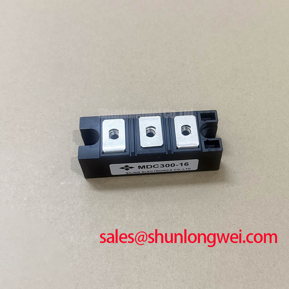
Before energizing a replacement assembly, verify the MDC300-16 marking, inspect the power terminals and mounting base, and compare the nameplate ratings with the rectifier position in the equipment. The IXYS MDC300-16 is a dual diode module specified for high-current rectification, with a 1600 V repetitive peak reverse voltage, a 300 A average forward current at Tc = 100°C, and a 150°C maximum junction temperature. These are official specification values for initial electrical screening; the complete application decision still depends on the converter topology, cooling path, protection network, and operating waveform.
| Parameter | Official Specification |
|---|---|
| Manufacturer | IXYS |
| Product category | Dual Diode Module |
| Repetitive peak reverse voltage, Vrrm | 1600 V |
| Average forward current, If(av) | 300 A at Tc = 100°C |
| Maximum junction temperature, Tj | 150°C |
Mechanical installation directly affects the thermal path from the module base to the heatsink. For the MDC300-16, clean both mating surfaces, check that the heatsink is flat and free from burrs, and spread the approved thermal interface material consistently. The objective is uniform contact pressure across the baseplate, not maximum clamping force. Uneven pressure can increase local thermal resistance or distort the module package.
The exact mounting torque, terminal torque, baseplate geometry, and thermal resistance values should be taken from the applicable IXYS mechanical and thermal data for the specific package revision. They should not be inferred from the 300 A current rating. Tighten the mounting hardware progressively in a crosswise sequence when multiple fasteners are used, then connect the power terminals without allowing the busbar to impose mechanical stress on the module.
During commissioning, measure temperature at the heatsink and assess the junction-temperature margin using the actual load profile. The official 150°C Tj maximum is an absolute device boundary, not a target operating temperature. Designers should verify conduction losses, cooling airflow or coolant conditions, contact quality, and cabinet temperature together. If the rectifier forms part of a high-current green hydrogen electrolyzer DC power supply, the current-sharing arrangement and ripple waveform should be checked under the real electrolyzer load rather than under a resistive bench load.
Where the rectifier is coordinated with a larger conversion stage, the nearby DDB6U180N16RRP_B37 can be reviewed as an example of a related power-stage module. Its electrical role must be evaluated separately; it is not an automatic substitute for the MDC300-16.
Assembly Integrity & Layout Architecture: Coordinating Surge Protection for MDC300-16
AC input protection should be coordinated with the rectifier’s repetitive reverse-voltage rating and the installation’s prospective fault energy. A MOV network, primary spark gap, line fuse, and any RC snubber should be assessed as one protection system. The 1600 V Vrrm rating confirms the repetitive reverse-voltage class of the diode module, but it does not define the correct MOV voltage, clamping level, surge current, or coordination point for a particular mains system.
As a design consideration, the surge protection network should limit the voltage appearing across the diode junctions while avoiding excessive leakage or repeated MOV conduction during normal operation. The protection loop should be physically compact, with short connections between the surge-limiting device, bus structure, and rectifier terminals. Parasitic inductance can raise the measured transient voltage, so validation should use a suitably rated differential probe and an oscilloscope during controlled switching and surge tests.
RC snubber selection is system-determined. The engineer should verify capacitance voltage rating, resistor pulse capability, damping behavior, and the effect of the network on leakage and commutation. The MDC300-16 datasheet or approved application documentation should be used for any specified fuse coordination, surge-current data, terminal arrangement, and recommended mounting hardware. Do not treat a generic MOV or snubber value as an official parameter of this module.
Bench Diagnostic: Isolate the equipment and discharge the DC link before removing power connections or probing the rectifier terminals.
Sinusoidal 10 ms Half-Cycle Surge Current Guidelines for MDC300-16
A short-duration overload must be evaluated against the manufacturer’s declared non-repetitive surge-current data, commonly identified in power diode documentation as IFSM. The supplied factory parameter set confirms the MDC300-16 voltage, average-current, and junction-temperature ratings, but it does not provide an IFSM value or a recovery interval. Those figures must be verified from the applicable IXYS datasheet before using the module in a fault-current or inrush calculation.
For a sinusoidal half-cycle event, record the actual peak current, duration, repetition rate, initial junction-temperature condition, and reverse-voltage reapplication timing. A single high-current pulse and repeated charging pulses impose different thermal stresses. The 300 A If(av) rating at Tc = 100°C should not be interpreted as a permissible 10 ms surge-current value. Engineers should compare the measured event with the manufacturer’s IFSM and I²t limits, then confirm that the device remains within its specified limits when reverse voltage is reapplied.
Temperature assessment should include the full thermal path: junction to case, interface material, case to heatsink, and heatsink to ambient or coolant. Semiconductor carrier behavior and recombination affect switching recovery and charge removal; background technical context is available in Carrier Lifetime and Recombination in Power Semiconductor P-N Junctions. This reference does not replace the IXYS device data or a measured waveform assessment.
For engineers comparing related high-power rectifier options, MSKD36-18 may be reviewed as a separate reference product. Its ratings, mechanical construction, and dynamic behavior must be checked independently before any compatibility decision.
MDC300-16 Fuse Coordination: Total Clearing I²t versus Device Surge Limits
Fuse coordination is intended to limit fault energy before the semiconductor reaches an unsafe thermal or mechanical condition. The relevant comparison is between the fuse’s total clearing I²t, including its interruption behavior, and the diode module’s specified surge-current and I²t limits. Neither the 1600 V Vrrm value nor the 300 A If(av) value supplies the missing fuse-coordination limit.
Obtain the applicable surge-current and I²t data for the MDC300-16 revision and compare them with the installation’s available fault current, DC-link capacitance, line impedance, and prospective clearing time. The fuse voltage rating, interrupting capability, pre-arcing I²t, total clearing I²t, and physical conductor inductance all influence the result. The system engineer should verify the worst-case fault waveform rather than relying only on a catalogue current label.
During validation, inspect the module after controlled protection tests for terminal movement, baseplate contact changes, package damage, and abnormal leakage. Thermal sensors should be positioned so that they reveal the heatsink response without being mistaken for a direct junction measurement. The 150°C maximum junction temperature remains the official device boundary, while the acceptable operating margin is determined by the equipment designer through thermal testing, protection coordination, and the required duty cycle.
For broader background on semiconductor switching structures and failure mechanisms, engineers can consult The Ultimate IGBT Knowledge Base. Its general principles should be applied alongside the specific IXYS MDC300-16 datasheet and the measured protection performance of the finished rectifier.