
Content last revised on September 20, 2026
Preventing Spurious Faults: Minimizing Commutation Turn-Off Voltage-Spike Guidelines for VBE60-06A
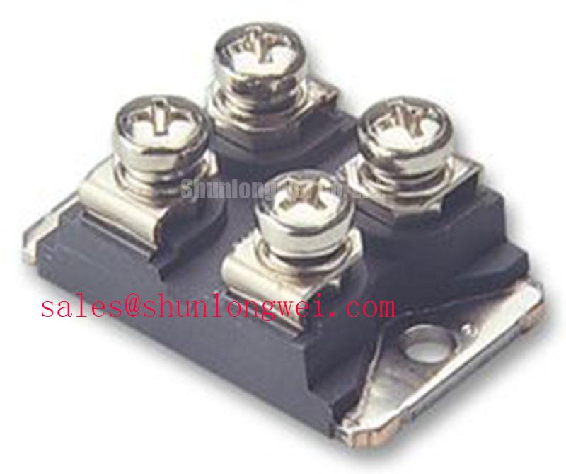
With the unit isolated from the circuit, first compare its terminal-to-terminal diode-mode readings in both polarities against the original connection diagram and a known-good device where available. The VBE60-06A is an IXYS dual diode module rated at 600 V and 60 A, supplied in the SOT-227B / TO-240AA housing. These are official datasheet specifications and define the electrical identity that must be matched before installation or fault analysis.
| Manufacturer | IXYS |
| Product type | Dual diode module |
| Voltage rating | 600 V official datasheet specification |
| Current rating | 60 A official datasheet specification |
| Housing | SOT-227B / TO-240AA official datasheet specification |
Before interpreting commutation behaviour, confirm that the installed part is the VBE60-06A dual diode module rather than an active switching or gate-controlled device. Its documented 600 V blocking rating and 60 A current rating provide the first boundary for reviewing rectifier or freewheeling positions in a power circuit. A diode-mode test can help identify an open path, an unexpectedly low-resistance path, or a polarity mismatch, but readings should be compared with the circuit topology because parallel paths and attached capacitors can alter the result.
Reverse-recovery peak current and recovery-time values are not included in the provided official parameter set. They should therefore be taken from the controlled manufacturer documentation for the exact part before any switching-loss or conducted-noise calculation is made. Do not assign a soft-recovery classification from package appearance or from a static meter reading. In an induction-heating supply, a measured ringing event can involve the diode, transformer leakage inductance, busbar layout, snubber network, and measurement probe placement.
Fuse coordination also requires the applicable device I2t information and the selected fuse time-current documentation; neither can be inferred from the 60 A rated current. Design Consideration: keep the commutation loop physically compact where the system layout permits, then verify voltage peaks at the module terminals under the actual load and control sequence. The terminal connection arrangement should be checked against the original equipment schematic before energisation.
💡 Bench Tip: Discharge the DC-link capacitors, use ESD-safe handling, and record cold-state diode readings before loosening or reconnecting module terminals.
VBE60-06A Operational Boundaries: Evaluating Phase-Controlled Rectification and Firing-Angle Limits
The VBE60-06A is specified here as a dual diode module, so it has no firing-angle control function of its own. Phase-controlled rectification from zero through high firing angles applies to thyristors or other controllable devices in the wider converter, not to this diode module. If the furnace power supply contains phase-control hardware, technicians should distinguish the diode commutation path from the separately controlled semiconductor path before attributing a low DC output or unstable current to the VBE60-06A.
Within a line-fed rectifier assembly, the diode’s role can still affect waveform continuity and thermal loading. An open diode path may alter the observed DC ripple, while a shorted path can change transformer-current symmetry or protective-device behaviour. Those observations are diagnostic starting points rather than conclusive proof. Verify the isolated module, continuity of the associated conductors, and the voltage waveform against a known-good signal path using correctly rated test equipment.
Engineering Recommendation: assess the 600 V rating against the highest repetitive and transient reverse voltage measured or specified for the complete system. The converter’s source impedance, transformer arrangement, firing control, and protection network determine actual stress. Reactive-power demand and power factor remain system-level characteristics and cannot be calculated from the module’s voltage and current ratings alone.
For a cross-model review, the MSKD36-18 listing can be used as a neutral reference point for comparing documented package, topology, terminal arrangement, and ratings. A replacement decision should only follow a full electrical and mechanical compatibility review.
Assembly Integrity & Layout Architecture: Implementing Thermal and Layout Considerations during High-Peak Operation for VBE60-06A
Inspect the SOT-227B / TO-240AA contact faces, mounting surface, terminals, and cable lugs before fitting the VBE60-06A. Flatness, cleanliness, and secure conductor routing affect interface resistance and the repeatability of electrical checks. The available official information identifies the housing but does not provide a mounting-torque value, thermal-resistance curve, transient thermal impedance network, avalanche rating, sinusoidal surge-current rating, or junction-temperature limit. Those values must be verified from controlled IXYS documentation for this exact device.
It is not valid to treat a diode module as avalanche-rated without an explicit manufacturer specification. Likewise, a 10 ms half-cycle surge assessment requires the applicable ITSM rating, initial junction condition, circuit waveform, and fuse coordination data. Where a furnace supply produces repetitive high-current pulses, the system integrator should check the measured current waveform and reapplication voltage against the complete approved design limits.
Design Consideration: apply thermal interface material uniformly according to the equipment manufacturer’s assembly procedure, avoid trapped debris, and tighten hardware using the documented torque for the actual fastener and module assembly. Thermal performance must be validated through heatsink and operating-condition testing rather than estimated from the package designation alone. For broader discussion of switching-device technology trade-offs and design constraints, see Wide Bandgap Revolution.
VBE60-06A Operational Boundaries: Evaluating AC-Line Surge Immunity and Lightning-Transient Limits
AC-line surge resilience belongs to the complete power-input assembly. The VBE60-06A has an official datasheet specification of 600 V, but this alone does not establish immunity to lightning or surge test waveforms. MOV selection, RC snubber design, upstream fuse behaviour, earthing arrangement, transformer coupling, and conductor geometry can all affect the reverse voltage presented to a diode module.
When reviewing a medium-frequency induction melting or hardening furnace power source, inspect the surge-protection path as an assembly: check whether protective components are damaged, verify their connection points, and observe whether clamp action is coordinated with the upstream protective device. Any proposed protection network should be validated during controlled system testing against the applicable equipment requirements. No standalone EMC compliance, insulation reliability level, or surge-certification claim should be assigned to this diode module without the relevant manufacturer or system-level evidence.
Measurement circuits deserve the same scrutiny as the power path. DC current transducers using fluxgate principles can support low-drift current observation when correctly integrated; the operating principle is described in this fluxgate reference. If an analogue conditioning stage is used, stability of its feedback network can influence displayed or controlled current, as outlined in this operational-amplifier reference. Check sensing integrity before treating a control alarm as evidence of a diode-module failure.