Content last revised on October 27, 2026
1DI15A-060 Inspection and Evaluation
- Isolate the power stage, verify that stored energy has discharged, and record cold collector-to-emitter readings before disconnecting the 1DI15A-060.
- Identify the base-drive and emitter-return connections from the equipment schematic before attaching test leads.
- Inspect terminal joints, mounting surfaces, and the heatsink interface for looseness, contamination, or uneven contact.
- Compare measurements with an unaffected equivalent circuit position; a single resistance reading does not establish serviceability.
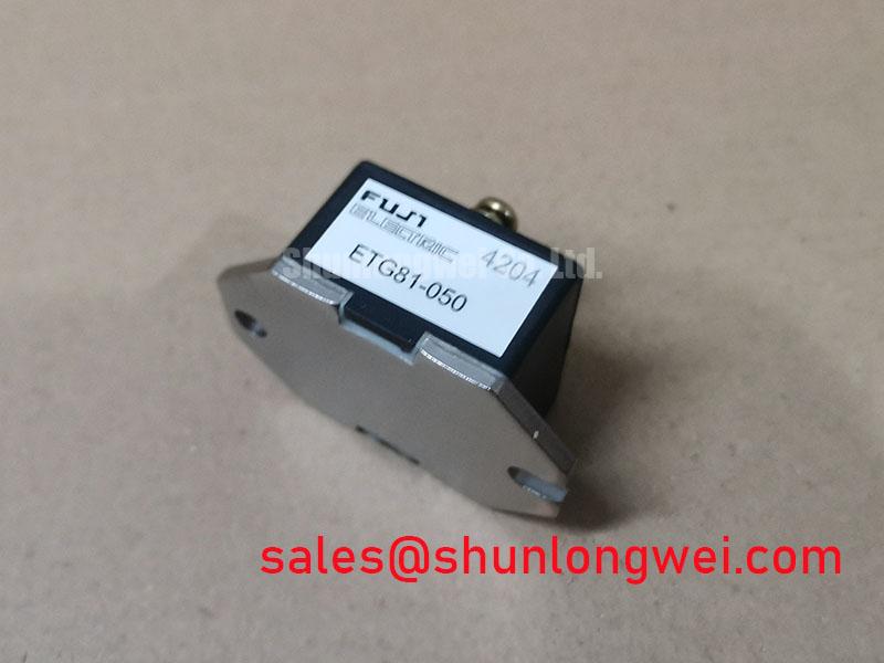
The Fuji Electric 1DI15A-060 is a power transistor / Darlington module, not an insulated-gate device. That distinction matters during repair: base-current delivery and charge removal govern its drive requirements, so IGBT gate-drive assumptions are not transferable.
| Official Specification | Symbol | Rated Value |
|---|---|---|
| Collector-emitter voltage | VCEX / VCEO | 600 V |
| Continuous collector current | IC | 15 A |
| Collector power dissipation | PC | 100 W |
| Operating junction temperature | Tj | −40 to +150 °C |
These are individual official ratings, not a simultaneous operating point. Consult the manufacturer datasheet for rating conditions, terminal assignments, safe operating area, package dimensions, and mounting requirements.
Transient Dynamics & Electrical Design: Transient Thermal Impedance on 1DI15A-060
Capture the overload duration and case-temperature history before assessing a pulsed-load shutdown. Design Consideration: a case measurement alone cannot resolve the junction-temperature excursion during a short load pulse, and the 100 W dissipation rating does not establish permissible pulse energy.
For a constant-power rectangular pulse, the engineering calculation is junction-temperature rise equals pulse dissipation multiplied by junction-to-case transient thermal impedance at that pulse duration. Add the measured case temperature to assess the peak against the +150 °C junction limit. Repetitive pulses require the accumulated thermal response, rather than restarting the calculation from a cold junction each cycle.
Use device-specific transient curves or validated thermal-network coefficients for that assessment. As a Design Consideration, Foster and Cauer networks represent thermal response differently; the general thermal impedance reference provides background, not coefficients for this module. Do not assemble an apparently precise model from unrelated device data.
Check heatsink flatness, interface coverage, and airflow obstruction before attributing overheating to the transistor. General eutectic-system principles explain material phase behavior, but do not establish an Au-Sn die-attach composition for this product; field servicing should remain focused on accessible mounting interfaces.
Benchtop Waveform Tuning: Mitigating Stress via PCB Gate Loop Layout Symmetry on 1DI15A-060
Trace the actual base-drive loop rather than treating the board as a gate-driven circuit. Design Consideration: shared emitter-path inductance can disturb the voltage seen by the driver as load current changes. A short, closely coupled base-drive and return path can reduce that disturbance, subject to the equipment’s routing and isolation requirements.
Layout symmetry is useful only where the circuit requires matched paths; it does not replace control of shared return impedance. This module’s supplied specifications do not establish a dedicated Kelvin-emitter terminal. A PCB return routed separately to the documented emitter connection must not be described as an additional internal module pin.
During controlled switching tests, observe collector-emitter voltage, collector current, and base-drive behavior with suitable probes. Relate ringing to the switching event before changing damping or suppression components. The Stray Inductance, Transient Voltage Overshoot reference supports assessment of loop-induced stress; final suppression choices depend on measured waveforms and the system operating envelope.
If switching frequency increases, reassess switching loss, charge-removal behavior, case temperature, and cooling performance together. No frequency-dependent derating curve follows from the ratings above. An existing MOV or snubber should be evaluated within its actual circuit role, not presumed capable of absorbing every local switching transient.
Field Diagnostics & Commissioning: Separating Driver Return from Main Current in 1DI15A-060 Topologies
Follow the driver-return conductor to its physical emitter connection and identify any section shared with load current. Engineering Recommendation: compare the driver-side reference with the module-side emitter during a controlled test to distinguish return-path disturbance from a genuine drive-command change.
Field Alert: Verify discharge before moving connections, and follow the documented mounting procedure rather than guessing tightening torque.
For possible integration into light-industrial automation or multi-joint robotic drives, compare the original power-stage schematic, base-drive capability, protection behavior, and mechanical interface. Check charge-removal timing and any complementary-switch interlock against observed current decay; an IGBT dead-time setting is not automatically suitable for a Darlington stage.
A comparison with 6DI150A-050 should begin with circuit configuration and terminal mapping, not a similar part-number family. Treat it as a separate product for evaluation, not a drop-in substitute. After installation, validate drive-return behavior and thermal contact under controlled loading before returning the equipment to normal operation.