


Content last revised on November 12, 2026
S20VTA60 Bridge Rectifier: Identification and Inspection
- Isolate the supply, verify DC-link discharge, and disconnect parallel current paths before measuring terminal-to-terminal resistance or diode conduction.
- Match the terminal markings to the equipment schematic before reconnecting incoming phases and DC output conductors.
- Inspect the mounting surface, thermal interface, terminal hardware, and surrounding insulation for damage or contamination.
- Compare forward and reverse readings between equivalent current paths, recording the meter polarity and component temperature.
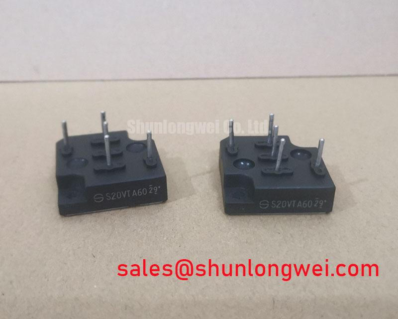
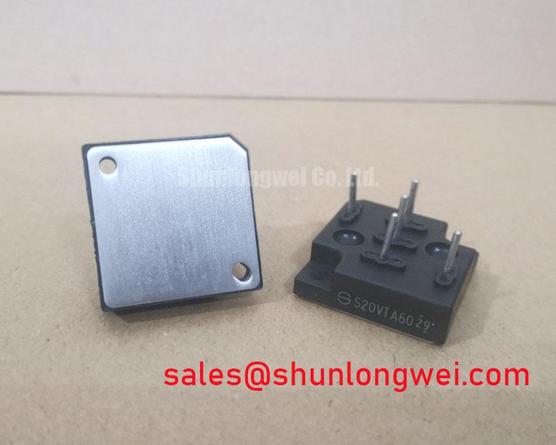
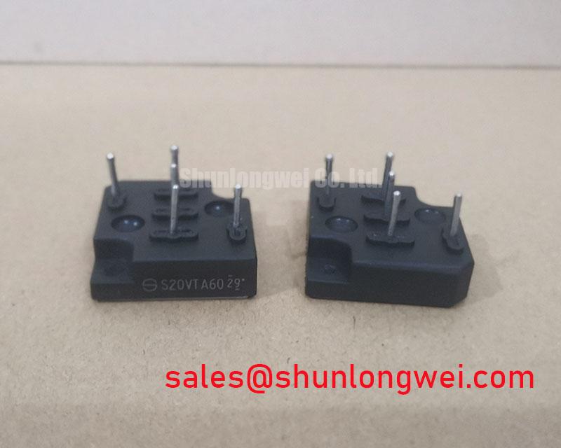
The S20VTA60 from Shindengen is a Bridge Rectifier Module with the electrical and configuration baseline below. For repair assessment, keep reverse-voltage capability, average conduction current, circuit configuration, and mechanical compatibility as separate acceptance checks.
| Specification | Product value |
|---|---|
| Manufacturer | Shindengen |
| Part Number | S20VTA60 |
| Repetitive Peak Reverse Voltage (VRRM) | 600.0 V |
| Average Rectified Output Current | 20.0 A; subject to the manufacturer's specified rating conditions |
| Device Type | Three-Phase Bridge Rectifier |
| Configuration / Topology | Diode Bridge |
| Additional integration data | Consult the datasheet for the circuit diagram, terminal assignments, rating conditions, available recovery data, surge withstand, thermal data, dimensions, and mounting requirements. |
The S20VTA60 is an uncontrolled diode bridge and does not require gate-trigger signals. Confirm terminal assignments from the manufacturer’s connection diagram before making connections.
Transient Dynamics & Electrical Design: Reverse Recovery and Temperature in S20VTA60
Capture commutation current and reverse voltage together when investigating ringing or excessive rectifier heating. Design Consideration: reverse recovery depends on junction temperature, preceding forward current, and the external commutation conditions. A waveform taken under light load cannot establish behavior at the equipment’s hottest operating condition.
Peak reverse recovery current and recovery duration describe different aspects of the transient; recovery softness concerns the current waveform’s decay rather than duration alone. Compare traces under consistent measurement conditions, with probe connections arranged to limit measurement-loop pickup. Switching noise can originate elsewhere in the power stage, so correlate the disturbance with the actual rectifier commutation event before assigning a cause.
The 600.0 V repetitive reverse rating is the relevant supplied voltage parameter; it is not an IGBT collector-emitter rating. Evaluate measured reverse peaks against that boundary under the system’s operating conditions. Keep conductor loops compact to reduce inductive voltage excursions, with the final arrangement determined by terminal geometry, insulation requirements, and measured behavior.
Engineering Recommendation: Keep corresponding phase connections geometrically balanced where practical, and validate the resulting commutation peaks at the intended operating conditions.
For topology comparisons, SKD 33/16 provides another rectifier reference, not an established drop-in replacement. Compare its internal circuit, terminal arrangement, cooling requirements, dimensions, and protection coordination before considering interchangeability.
S20VTA60 Operational Boundaries: Fault Protection and Coordination
Compare the protective device’s total clearing I²t with the semiconductor’s permitted withstand under matching fault conditions. Design Consideration: prospective fault current, circuit voltage, initial junction temperature, and fault duration all affect this comparison. Average current alone cannot establish short-circuit survival.
Prepare a coordination worksheet containing the manufacturer’s non-repetitive surge-current conditions, semiconductor I²t limit where specified, fuse total clearing data, and the installation’s prospective fault current. Distinguish fuse pre-arcing data from total clearing data; the latter includes the interruption interval relevant to semiconductor exposure. No calculation from the supplied ratings supports a guarantee of damage-free fault clearing.
Type-2 coordination concerns a defined equipment combination and its applicable assessment, not a standalone claim for this rectifier. Select protection using the equipment’s required coordination criteria and supporting test documentation. After a fault, assess the bridge, conductors, protection components, and insulation before returning the assembly to service.
Thermal recovery also matters after an overload. Use the applicable transient thermal impedance curve, where available, and actual pulse history to assess peak junction temperature; steady-state thermal resistance does not describe every short pulse. Mounting flatness, interface condition, and manufacturer-specified tightening torque influence the heat path, but no torque value follows from the package category alone.
When evaluating a high-current green hydrogen electrolyzer DC power rectifier, determine whether this component’s rating conditions and circuit role fit the proposed subsystem rather than the overall plant current. The VVZB135-16IOXT is a separate power-conversion component for topology comparison; its suitability as a front-end or auxiliary-stage device depends on its own circuit and system requirements.
Field Diagnostics & Commissioning: S20VTA60 Diode-Bridge Checks
Use the documented internal circuit to identify the diode paths before testing. Design Consideration: gate-trigger, latching-current, and holding-current tests apply to thyristors, not to the S20VTA60 diode bridge. If the equipment contains a separate controlled-rectifier stage, assess its firing circuit against that stage’s own device specifications.
Cold multimeter comparisons can reveal asymmetric conduction paths, but surrounding snubbers and connected loads can influence readings. Separate those paths before interpreting differences. Inspect terminal spacing and insulation surfaces without treating a clean appearance as proof of dielectric performance.
Where the assembly includes a downstream switching stage, the IGBT vs. MOSFET Technical Reference provides context for distinguishing transistor gate-drive issues from rectifier commutation faults. During recommissioning, correlate phase currents, DC output, and temperature rise; assess firing-angle harmonics only where a separate phase-controlled stage is confirmed by the circuit.