Content last revised on September 10, 2026
LQ150X1LW72 Installation and Compatibility Verification
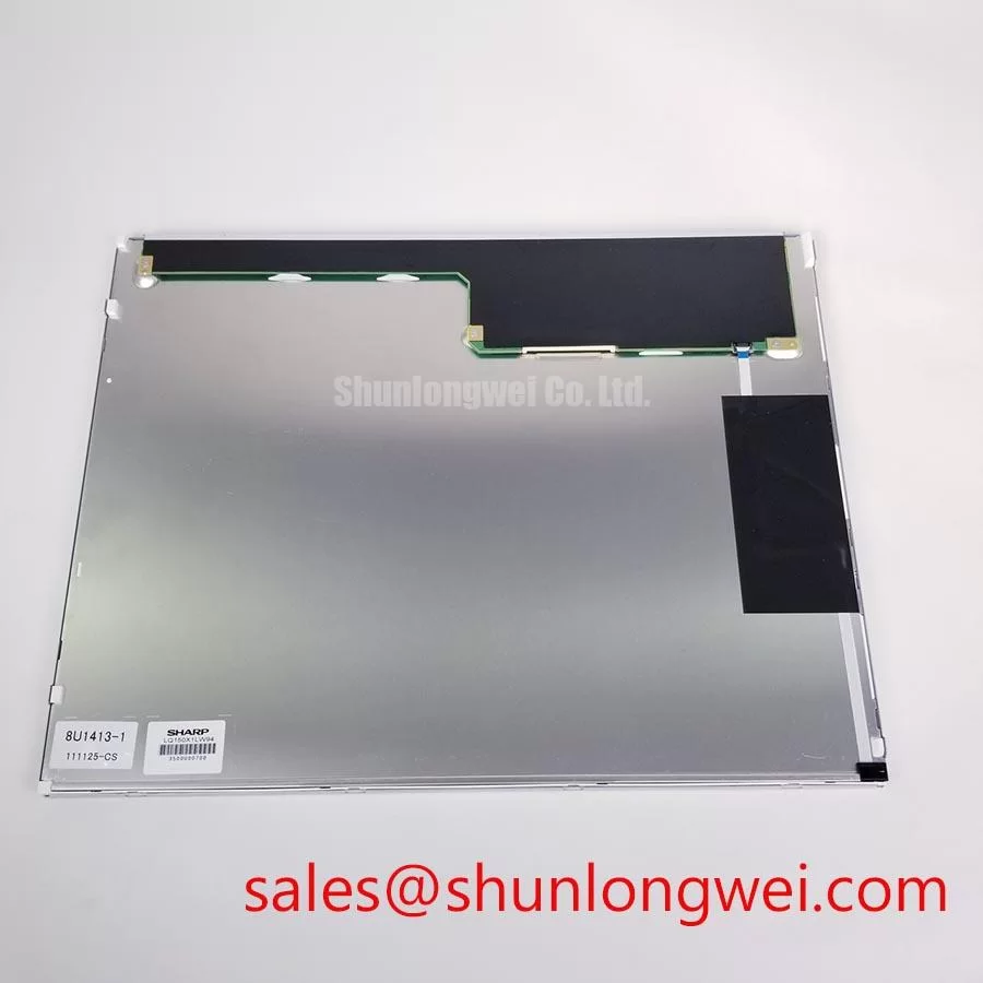
Before installation, inspect the LQ150X1LW72 label, bezel condition, mounting ears, display connector, and cable-retention features against the removed panel while power is isolated. This Sharp TFT-LCD Display Module is identified as an Industrial Grade LCD/HMI Panel with Official Factory Spec Verified status. The supplied official product data confirms the model, manufacturer, product category, and module form factor; electrical input rails, interface assignment, native resolution, optical values, backlight architecture, and environmental limits must be verified from the original equipment documentation before a replacement is energized.
For repair work, model identity alone is only one part of compatibility. The host controller must match the panel’s actual signal interface, timing format, connector pinout, mechanical datum positions, and backlight supply arrangement. A display can physically fit an enclosure while remaining electrically unsuitable for the controller board. Treat the original harness, panel documentation, and host-board signal measurements as the controlling references for integration.
| Item | Verified Product Information |
|---|---|
| Model | LQ150X1LW72 |
| Manufacturer | Sharp |
| Product category | Industrial Grade LCD/HMI Panel |
| Module form | TFT-LCD Display Module |
| Specification status | Official Factory Spec Verified |
| Integration data requiring host-document verification | Signal interface, display timing, supply rails, backlight requirements, connector assignment, optical performance, touch implementation, and environmental ratings |
Chassis M3 Fastener Torque Sizing (0.35–0.45 N·m) to Reduce Optical Mura Risk
Mount the LQ150X1LW72 only after checking that the replacement chassis presents an even bezel landing surface and that no cable, gasket, screw head, locating post, or rear support bears concentrated load on the active display area. Uneven mechanical loading can appear as local brightness variation, pressure marks, or color variation when the image is viewed against a dark or neutral background. These visual effects are installation-related observations, not a declared Sharp optical specification for this model.
A cross-pattern tightening sequence is a useful Design Consideration for assemblies using M3 chassis hardware. A 0.35–0.45 N·m torque range is a general assembly reference for controlled M3 fastening where the enclosure, threaded insert, washer stack, and bezel design have been validated. It is not an official torque rating for the LQ150X1LW72. The equipment owner should follow the original mechanical drawing and confirm that the final torque does not distort the bezel or transfer load to the panel edges.
⚠️ Field Alert: Do not tighten one corner to its final torque before the remaining M3 points are seated, because an uneven clamp sequence can create localized stress that becomes visible only after the display is powered.
The outer bezel opening deserves the same care as the screw pattern. Its edge clearance should accommodate panel placement without rubbing, while retaining the module without compressing its visible region. During a service replacement, compare the old and replacement panel orientation, locating features, and cable exit direction before committing the fasteners. If a newly installed screen shows a pressure-related visual irregularity, loosen the mounting hardware in a controlled sequence, reassess panel seating, and inspect the enclosure rather than assuming an electrical fault.
Where the host board uses a differential display link, transmitter clock quality and receiver timing margin remain system-level requirements. The required interface could be LVDS, TTL, or another panel-specific scheme; the system integrator should verify the actual interface from the original panel documentation rather than infer it from the product family name. If LVDS is confirmed, the transmitter format also needs alignment with the required JEIDA or VESA mapping. A panel that receives valid-looking clock activity but the wrong data mapping may produce incorrect colors or abnormal image structure.
During bench validation, compare clock and data waveforms with a known-good signal path where possible. Observe whether the panel is released from reset and enabled in the required power sequence, then confirm that the controller provides stable timing over the equipment’s intended operating conditions. This is an Engineering Recommendation: measure the actual host timing relationship rather than relying on a visual assumption that a connector-compatible panel will accept the same signal format.
Full-Screen Primary Color Inspection: Stuck Sub-Pixels & Background Uniformity Audit
Perform an incoming inspection with controlled full-screen red, green, blue, white, black, and mid-gray images before returning the equipment to service. The inspection should begin at normal viewing distance, followed by close observation of the active area and border regions. A primary-color sequence helps reveal pixels that remain fixed, while white and gray fields help make broad nonuniformity, isolated bright points, or gradual shading easier to see.
A practical three-stage bench routine is to display solid primary colors first, inspect black and low-gray fields second, and review white or neutral-gray fields third. Record the panel orientation, image source, cable used, brightness setting, and ambient condition with the inspection result. This documentation helps distinguish repeatable panel behavior from artifacts introduced by a test fixture, controller, cable, or an enclosure surface.
Use a low-angle inspection light with care. Holding a flashlight at approximately 45 degrees across the front surface can make front-polarizer marks, surface contamination, or reflections easier to separate from a luminous defect. It does not establish the root cause of a line or shadow. A persistent line that follows the displayed image across multiple color fields may warrant verification of the signal source, connector seating, and host timing. A region that changes with backlight control or physical mounting condition may warrant separate evaluation of the illumination system and mechanical support.
The official structured data supplied for the LQ150X1LW72 does not specify contrast ratio, sunlight readability, anti-glare treatment, or a luminance test condition. Therefore, claims such as a contrast ratio above 500:1 at 50,000 lux cannot be assigned to this model from the available verified information. For equipment exposed to strong bridge-console or outdoor-adjacent ambient light, designers should evaluate the completed display assembly under its actual enclosure window, viewing angle, ambient reflections, and user task conditions.
Touch behavior should also be kept separate from the LCD module assessment. The available official product information does not confirm that this Sharp module includes a touch panel. If the host equipment uses a resistive or projected-capacitive overlay, glove operation, moisture response, front glass thickness, controller firmware, and grounding arrangement belong to the system-level touch assembly. Verify these functions with the original overlay and controller documentation rather than assigning touch performance to the LQ150X1LW72 itself.
Servo drives, switching power supplies, and motor cables can introduce noise into nearby display wiring. If flicker, intermittent color behavior, or image instability appears only when high-power equipment is active, inspect the ground return, connector retention, cable routing, shielding termination strategy, and host signal integrity. The symptom can have several interacting causes, so oscilloscope comparison against a stable operating state is more informative than a single-cause diagnosis.
Optical Luminance Degradation Considerations & CCFL-to-LED Modernization Retrofit Pathways
Do not assume the LQ150X1LW72 uses either CCFL or LED illumination without its applicable panel documentation. The verified product description identifies a TFT-LCD module but does not state its backlight technology, lamp count, LED configuration, driver topology, ignition requirement, dimming method, or expected luminance retention. These details are essential because a backlight connector can carry energy levels and control signals that are not interchangeable between different module generations.
Older display platforms sometimes use high-voltage lamp inverter assemblies, while newer platforms often use constant-current LED driver arrangements. That broad industry distinction is a Design Consideration, not a declared construction detail for this Sharp panel. A modernization project must begin with identification of the original panel’s illumination interface and the host system’s enable and dimming logic. Replacing only the display module while retaining an unverified illumination supply can create an immediate compatibility issue.
When evaluating a retrofit, verify the panel supply sequence, display-data enable sequence, backlight enable behavior, dimming control method, connector keying, and protective shutdown response at the equipment level. The retrofit assembly should be tested for image stability across the intended brightness range and after repeated power cycling. Acoustic noise, delayed illumination, uneven brightness, and unstable startup are observable service findings that should lead to measurement and documentation, not assumptions about a specific internal lamp or driver defect.
If the original host interface is confirmed as LVDS, controlled differential routing is a common Engineering Recommendation. A nominal 100 Ω differential impedance is widely used for LVDS channels, subject to the host interface requirement, cable structure, connector choice, and PCB stackup. Keep paired conductors geometrically consistent to reduce mode conversion and clock-related image sensitivity, then verify the finished system using appropriate signal-integrity measurement.
💡 Pro Tip: Route confirmed differential clock and data pairs with consistent pair geometry and matched electrical path behavior, then validate display stability while the surrounding motion-control and power-conversion equipment is operating.
Selection discussions should remain physical and electrical rather than name-based. The LMS700KF01-001 can be reviewed as a separate display option during an engineering comparison, but its mechanical dimensions, interface, timing, illumination requirements, optical characteristics, and cable compatibility must each be checked against the LQ150X1LW72 host design. It should not be treated as a drop-in substitute without those checks.
For equipment documentation or service workflows that reference related Sharp display assemblies, the LQ150X1LG11 is another separately identified panel model that may be useful for catalog comparison. It does not establish electrical or backlight interchangeability with the LQ150X1LW72.
Managing Localized Thermal Gradients and Potential Optical Color Shift
Start thermal troubleshooting by checking the installed display as part of the full enclosure. Examine whether nearby power devices, processor heat sinks, fan exhaust paths, sealed front windows, or cable bundles create asymmetric heating around the panel perimeter. A display can show color or brightness changes that are affected by temperature, mechanical compression, ambient illumination, or source timing. The service process should isolate these variables progressively instead of attributing every visual change to the panel itself.
Where the equipment enclosure includes edge rails or conductive supports, their role should be reviewed as a Design Consideration. A mechanically suitable rail can help distribute enclosure heat and avoid a concentrated edge hot spot, but its material, contact pattern, surface treatment, insulation needs, and allowable load must be determined by the equipment design. Direct contact with sensitive panel areas should not be introduced without a validated mechanical drawing.
The available official information does not define the optical materials, thermal limit, yellowing mechanism, L70 value, B50 value, or operational lifetime of the LQ150X1LW72. Consequently, no quantified life prediction or color-shift guarantee should be assigned to this module. For a long-running HMI, radar display, navigation-console terminal, or industrial monitoring screen, the system integrator should monitor actual enclosure temperature, display appearance, airflow state, and brightness behavior under representative duty conditions.
Power and signal routing should be examined together. High-current return paths, switching nodes, and motor wiring should be kept from coupling into confirmed low-voltage display signal paths where enclosure layout permits. The purpose is to reduce conducted and radiated disturbance that can affect image stability. Final routing, shielding, grounding, and filtering choices are determined by the complete equipment architecture and should be verified in the finished system.
For a structured troubleshooting approach covering panel installation, interface verification, enclosure effects, and display-system diagnostics, consult Industrial Display & HMI Solutions. In potential harsh marine radar and navigation bridge-console evaluations, enclosure sealing, salt exposure control, viewing-window reflections, cable strain relief, and thermal management should be assessed at equipment level; the supplied verified information for the LQ150X1LW72 does not independently certify the module for that environment.