

Content last revised on September 21, 2026
ETG81-050 Power Diode Bridge Module Evaluation
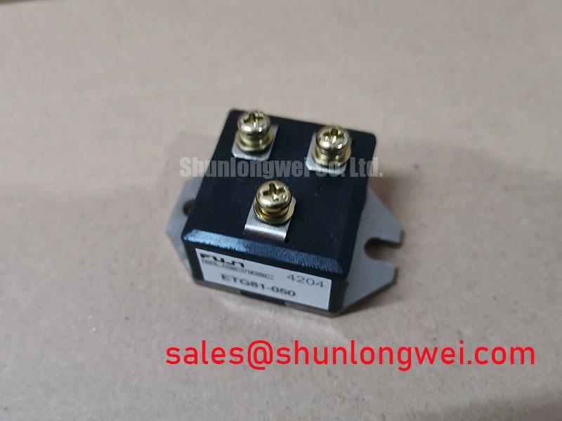
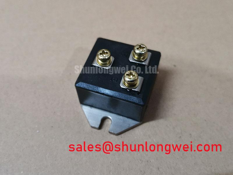
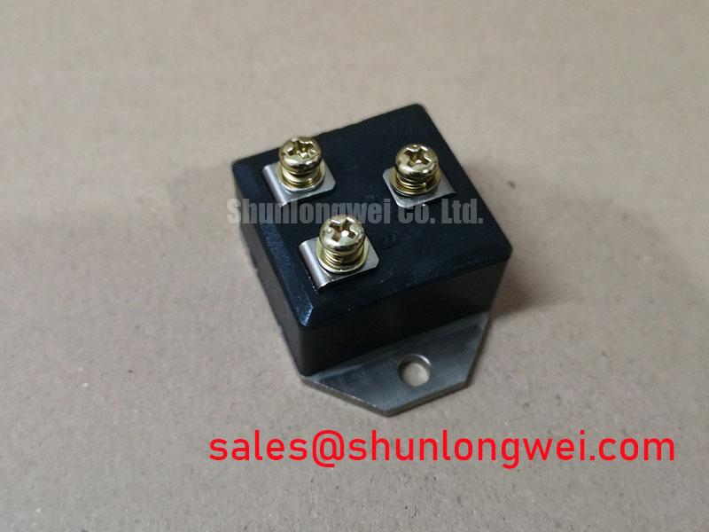
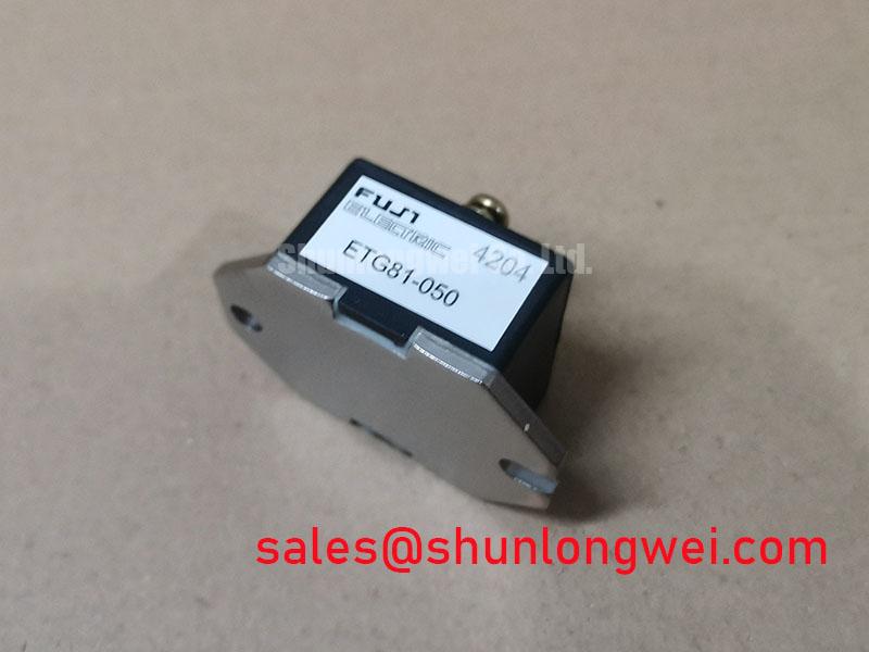
Before fitting the ETG81-050, isolate the rectifier assembly, inspect the module case and terminals for heat discoloration or cracking, and compare each AC and DC connection with the original equipment wiring record. This Fuji Electric unit is a Power Diode Bridge Module with an official repetitive voltage rating of 600.0 V and a rated current of 30.0 A. These are Official Datasheet Specifications and define the electrical identity that must be matched during repair evaluation.
As a diode bridge module, the ETG81-050 rectifies AC power to DC. It does not have a gate terminal, gate driver, Miller plateau, or a controllable firing angle. Any system using phase angle control requires upstream thyristors, active switching devices, or a dedicated controlled rectifier stage outside this diode bridge module. Fuji Electric’s wider power semiconductor portfolio provides useful context for evaluating power conversion assemblies, but the ETG81-050 itself should be assessed strictly as a fixed diode rectifier.
| Parameter | Specification | Classification |
|---|---|---|
| Manufacturer | Fuji Electric | Official product identification |
| Product model | ETG81-050 | Official product identification |
| Module category | Power Diode Bridge Module | Official product classification |
| Rated voltage | 600.0 V | Official Datasheet Specification |
| Rated current | 30.0 A | Official Datasheet Specification |
Transient Dynamics & Electrical Design: Critical Rate of Rise of Off State Voltage on ETG81-050
The first integration check is whether the rectifier’s measured AC line conditions, DC bus conditions, and expected transient peaks remain compatible with the 600.0 V official voltage rating. The rating should not be treated as a complete description of every transient condition. Cable inductance, transformer leakage inductance, contactor opening events, and load commutation can create momentary voltage excursions at a bridge module even when nominal line voltage appears acceptable.
In an uncontrolled diode bridge, the practical switching transition is diode commutation between phases. Unlike an IGBT or thyristor circuit, no gate loop exists to tune. The relevant Design Consideration is the current path formed by the transformer secondary, AC conductors, bridge terminals, DC busbars, surge suppressors, and load. Long or asymmetric conductors can add inductance and resistance, changing the voltage seen by individual bridge paths during current transfer.
When an RC snubber, surge suppression network, or series reactor is present in the original assembly, its function should be verified against the equipment schematic rather than copied by appearance alone. A snubber can reduce repetitive ringing caused by inductive current commutation, while a reactor can moderate current rise associated with transformer energization or load disturbances. Component values, dissipation limits, and placement are system determined and require waveform validation at the module terminals.
For a high current green hydrogen electrolyzer DC power rectifier, engineers should distinguish the ETG81-050’s bridge function from the larger system’s current regulation hardware. Electrolyzer supplies often include transformer taps, controlled rectifier sections, DC chokes, current sensors, and supervisory protection. The ETG81-050 can only be considered compatible when the actual branch current, AC source arrangement, thermal path, and fault clearing arrangement are documented.
Terminal connection quality deserves the same attention as voltage stress. Clean mating surfaces, correct conductor alignment, and even mechanical loading help maintain low resistance current paths. The manufacturer documentation available for this identification does not establish a mounting torque value, terminal screw size, fuse coordination table, or permissible wiring geometry. The system integrator should obtain those values from the original equipment documentation or the applicable Fuji Electric mechanical drawing before installation.
⚠️ Field Alert: Do not tighten module terminals or mounting hardware to an assumed torque because excessive or uneven mechanical force can damage a power module or compromise its electrical connections.
Where a same family electrical reference is required for documentation comparison, 2DI30D-050A is a separate Fuji Electric power semiconductor model that should be evaluated only by its own published pinout, topology, electrical ratings, and mechanical outline. A similar voltage or current label does not establish direct replacement compatibility.
Benchtop Waveform Tuning: Mitigating Stress via Evaluating Post Surge Reverse Voltage Blocking on ETG81-050
After an AC disturbance or surge event, a bridge diode must regain reverse blocking capability while the rectifier circuit returns to its normal voltage polarity sequence. For ETG81-050 assessment, use the 600.0 V official voltage rating as the primary published boundary, then observe the actual line to line and DC bus waveforms with properly rated differential measurement equipment. The test should capture source energization, normal load operation, load removal, and any event that has historically caused protection trips.
The available official parameters identify a 30.0 A rated current and do not provide a confirmed sinusoidal half cycle surge current value, reverse recovery characteristic, maximum junction temperature, thermal impedance, or post surge recovery interval. Those values must not be inferred from another Fuji Electric module or from a generic diode bridge chart. If surge rating verification is required for a repair decision, it should be based on the exact manufacturer datasheet or the original equipment protection specification.
A controlled bench evaluation starts with continuity and polarity checks while the module is disconnected from stored energy sources. Compare each measured forward conduction path and reverse blocking path with the bridge topology shown in the equipment drawing. A result that differs from the expected path can indicate several possible conditions, including external parallel circuitry, measurement lead placement, connection errors, or module damage. Isolate the module sufficiently to prevent surrounding components from masking the measurement.
During powered testing, confirm that the measurement reference is appropriate for the rectifier’s isolation arrangement. Probe ground placement, instrument bandwidth, and lead routing can alter an observed transient. Engineers should compare the waveform at the module terminals with the known good signal path where available, then determine whether ringing is generated locally by the bridge wiring or arrives from transformer, busbar, or load circuitry.
Thermal recovery after a current event should be evaluated through the whole assembly rather than by assuming a single thermal cause. Heatsink contact condition, airflow, enclosure temperature, conductor heating, current imbalance, and repeated line disturbances can all affect the measured result. Design Consideration calls for checking whether the module mounting surface is flat and clean and whether the original thermal interface arrangement has been retained. Any change to heatsink construction or cooling conditions requires system level validation.
A post surge reverse voltage test also benefits from reviewing the sequence of protective actions. The bridge may experience a short duration abnormal current before an upstream breaker, contactor, fuse, or controller responds. The exact sequence depends on the source impedance and protection architecture. For long term maintenance planning, the engineering discussion in Future of Power Electronics can help frame broader power conversion evaluation, while the ETG81-050 decision must remain tied to verified device ratings and measured installation conditions.
Benchtop Waveform Tuning: Mitigating Stress via AC to DC Transfer Characteristics across Voltage on ETG81-050
The ETG81-050 is an uncontrolled diode bridge. It conducts according to the instantaneous AC source polarity and the DC load condition, rather than according to a commanded firing angle. Therefore, a firing angle sweep from zero to one hundred and fifty degrees is not a tuning method for this module. If an electrolyzer power supply uses firing angle control, the relevant variable belongs to a separate controlled rectifier stage using thyristors or other controllable switching devices.
For this diode bridge, useful AC to DC bench observations include AC input waveform symmetry, DC ripple form, DC load current, voltage drop under load, and commutation disturbance at phase transitions. These observations should be made with the original AC source configuration and with safe test conditions appropriate to the equipment. The bridge may be part of a single phase or multiphase system, but the exact AC configuration should be confirmed from the original circuit documentation rather than assumed from the module designation.
Power factor and reactive power are also system properties. Transformer magnetizing current, source impedance, line reactor selection, DC smoothing inductance, load regulation, and upstream controlled devices can influence them. It would be inaccurate to assign a power factor value or reactive power demand to the ETG81-050 from its 600.0 V and 30.0 A ratings alone.
In maintenance work, compare AC input voltages at the bridge under the same operating state, then compare the DC output waveform at the bridge and at the load side of any DC choke or fuse. An abnormal difference can indicate a wiring issue, source imbalance, excessive connection resistance, downstream load behavior, or a bridge path problem. The measurement should be repeated only after the circuit’s discharge procedures and isolation state have been verified.
Design Consideration favors compact, balanced AC and DC conductor routing around the bridge where the existing equipment layout permits. This reduces loop area and helps suppress inductive voltage disturbance during diode commutation. 💡 Pro Tip: Keep paired high current conductors physically symmetric where practical, then verify terminal voltage peaks under the actual operating waveform before approving a layout change.
Long cable reflection effects are more commonly examined around fast switched inverter outputs than around a line frequency diode bridge. If the ETG81-050 is installed within an assembly that also contains inverter stages, those stages need separate testing because their switching edge rates, cabling, and suppression methods are outside the diode module’s published identity.
ETG81-050 Circuit Protection & Reliability: Calibrating I2t Sub Cycle Melting Rating
Fuse coordination begins by identifying the exact protection device and the exact fault path. The ETG81-050 has official ratings of 600.0 V and 30.0 A, but no verified I2t withstand value, fuse I2t coordination table, or fault current capability has been provided for this model. A semiconductor fuse selection cannot be calculated responsibly from the nominal module current alone.
In a bridge rectifier assembly, the fuse must be evaluated together with transformer fault current, source impedance, AC conductor capability, DC load energy, contactor behavior, and the bridge topology. Fuse datasheets normally distinguish pre arcing I2t from total clearing I2t. The relevant coordination exercise compares the actual prospective fault waveform and fuse clearing behavior against the published capability of every component in the fault loop. It should not be represented as a guaranteed zero damage outcome without manufacturer supported limits for the ETG81-050.
For an electrolyzer DC rectifier, dead short protection is particularly dependent on where the fault occurs. A fault at the DC output, inside a downstream choke, or on the AC feeder can produce different current paths through the bridge. Engineers should trace those paths on the schematic, identify which diodes conduct in each case, and verify protection response using the original system design documentation.
Reliability assessment should remain evidence based. No service life, failure rate, surge repetition capability, altitude behavior, EMC compliance, insulation certification, or cosmic ray performance claim should be assigned to this diode bridge without an applicable manufacturer document or recognized test source. Practical inspection can instead focus on terminal condition, heatsink interface, protection device condition, conductor discoloration, ventilation path, and measured operating waveforms.
When replacing a rectifier module, retain the equipment’s documented fuse class and protection arrangement unless a qualified system engineer has completed a new coordination study. Verify the module’s physical outline, terminal arrangement, circuit topology, voltage rating, current rating, cooling interface, and AC and DC connection designation before energizing the assembly.