Content last revised on September 27, 2026
2DI75A-140 Thermal-Electrical Optimization: Fuse Total Clearing I2t versus Device Melt Practical Tuning
In a grid-tied static Var compensator or thyristor-switched capacitor assembly, the semiconductor fuse must be evaluated against the complete fault-clearing behavior of the branch circuit. The published product information available for this page confirms the 1400.0 V rating, the 75.0 A rating, and the power diode bridge construction. It does not establish a fuse coordination value, device melt I2t limit, peak non-repetitive surge current, or permitted short-circuit duration. Those values should be taken from the applicable Fuji Electric datasheet and the selected fuse manufacturer’s coordination table before approval.
During service replacement, record the existing fuse class, voltage rating, current rating, prospective fault current, and total clearing I2t. Compare those values with the official diode-module limits for the exact production variant. A fuse that interrupts rapidly can still expose the rectifier to a damaging current pulse if its let-through energy is unsuitable. Conversely, selecting only by nominal amperage can overlook repetitive charging pulses from the capacitor branch. The system engineer should validate the protection arrangement with controlled testing and confirm that the fuse, busbar, and module terminals remain within their applicable ratings.
Terminal hardware should be cleaned and tightened according to the manufacturer’s installation documentation and the equipment builder’s procedure. A torque value is not provided in the supplied product data, so a generic number should not be presented as an official requirement for this model.
Field Diagnostics & Commissioning: Harmonic Current Injection and Line Filter in 2DI75A-140 Topologies
For commissioning, first isolate the diode bridge from the control and capacitor-switched sections, then confirm that the phase connections match the original circuit drawing. Measure the line-to-line and line-to-DC paths with the equipment fully isolated and discharged. A cold resistance reading alone cannot prove semiconductor health because the result depends on the meter method, connected components, and internal diode junction behavior. Compare equivalent paths and investigate asymmetry rather than assigning a single fault from one reading.
When harmonic current is injected during testing, monitor the current waveform at the module input and the DC-side ripple at the rectifier output. Abnormal distortion may involve the line reactor, filter network, capacitor branch, firing control, wiring impedance, or the diode bridge. Verify the signal path with an oscilloscope and compare it with a known-good operating record. The 1400.0 V voltage rating and 75.0 A current rating are official product specifications; they do not define the permissible harmonic spectrum, power factor, reactive power, or firing-angle behavior of the complete SVC installation.
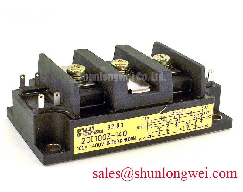
Engineers comparing a higher-current bridge option can review 2DI100Z-140 as a separate Fuji Electric product reference. It should be assessed against the original circuit’s voltage, current, mechanical, thermal, and protection requirements rather than treated as an automatic substitute.
Benchtop Waveform Tuning: Mitigating Stress via Junction-to-Heatsink Heat Dissipation in 2DI75A-140
Remove old thermal-interface material completely and inspect the heatsink for burrs, corrosion, bowing, or embedded debris before installing the replacement. The module base must sit evenly against the heatsink, with no foreign material that could create a local air gap. Apply only the thermal-interface method specified by the module documentation and verify that clamping does not distort the housing.
Thermal evaluation should use the actual rectifier current, switching or line-frequency duty, ambient condition, airflow, and enclosure arrangement. The supplied official parameter set does not include junction-to-case thermal resistance, case-temperature limits, thermal impedance curves, or allowable overload duration. These values must be confirmed from the manufacturer’s technical documentation before calculating a heatsink requirement. A thermal camera can help locate uneven contact or an overloaded terminal, but its emissivity setting and measurement position must be controlled.
Maintenance Note: Monitor contact temperature during scheduled inspections and recheck the heatsink airflow after cleaning, because dust loading and degraded thermal material can change the measured operating condition.
Assembly Integrity & Layout Architecture: Implementing Sinusoidal 10ms Half-Cycle Surge Current L for 2DI75A-140
A short-duration line surge test must be planned around the exact official surge-current and I2t data for the 2DI75A-140. No sinusoidal 10 ms surge-current rating is included in the supplied specifications, so it would be unsafe to infer one from the continuous 75.0 A rating. Before reverse voltage is reapplied, confirm the test source impedance, repetition rate, initial junction condition, fuse response, and cooling state against the manufacturer’s limits.
Keep the high-current path compact and mechanically supported, while maintaining the insulation clearances required by the equipment standard and enclosure design. Minimize parasitic loop inductance where it can create voltage overshoot, then verify peak voltage with suitable measurement equipment during switching and surge tests. The system designer must determine the required margin against the DC-link and line voltage after reviewing the measured waveform.
Gate-drive damping, Miller-platform charge, active clamping, negative off-bias, and single-event-burnout analysis apply to controlled IGBT switching devices and their installation environment. They should not be assigned as properties of this diode bridge module without supporting manufacturer data. For background on gate-drive protection principles, see Evolution of Negative Off-Bias Gate Drive Circuits. Product-family context is available from Fuji Electric Power Semiconductor & IPM Modules and the Fuji Electric global semiconductor site. Before release to service, verify the original circuit drawing, protection table, terminal layout, and complete Fuji Electric datasheet for the installed production variant.