Content last revised on August 31, 2026
Pulse-Transformer Isolated Firing Circuit Design for Medium-Voltage Thyristor Modules
When commissioning or troubleshooting industrial Grid-Tied Static Var Compensators (SVC) and Thyristor-Switched Capacitor (TSC) banks on 575V to 690V line supplies, high transient immunity is critical. The 6RI75G-160B by Fuji Electric is rated at a maximum blocking voltage of 1600V (Official Datasheet Specification), delivering substantial voltage headroom against transient line overvoltages during inductive bank step-switching. In these topologies, firing circuits relying on pulse transformers require steep gate pulse rise times to avoid localized junction hotspotting across the silicon die during turn-on transitions.
In high-power industrial cabinets, inductive gate-loop pickup from adjacent busbars can induce spurious gate triggering. Isolating firing circuits using double-shielded pulse transformers prevents common-mode noise transfer while maintaining a rapid initial gate current rise. Once initial latching occurs, sustaining gate conduction with a continuous or high-frequency pulse train guarantees that the device remains in full conduction across current zero-crossings, even under leading power factor conditions.
⚠️ Field Alert: During on-site replacements, always inspect the heatsink surface for burrs and clean off hardened compound before torquing. Apply an even 50–100 µm layer of high-grade Thermal Interface Material (TIM) across the copper baseplate. Uneven mounting torque or excessive grease thickness causes localized thermal pockets, quickly degrading silicon dies under rapid thermal cycling.
AC Line Surge Immunity, Lightning Transients & MOV Clamping Coordination
Static Var Compensator installations regularly encounter grid-side transients induced by lightning strikes or vacuum circuit-breaker restrikes. Safeguarding power semiconductor modules like the 6RI75G-160B against IEEE 61000-4-5 line surges requires coordinated secondary overvoltage protection. Because the module possesses a 1600V rating (Official Datasheet Specification), the primary Metal Oxide Varistors (MOVs) should clamp line spikes well below the module's absolute maximum rating under severe fault currents.
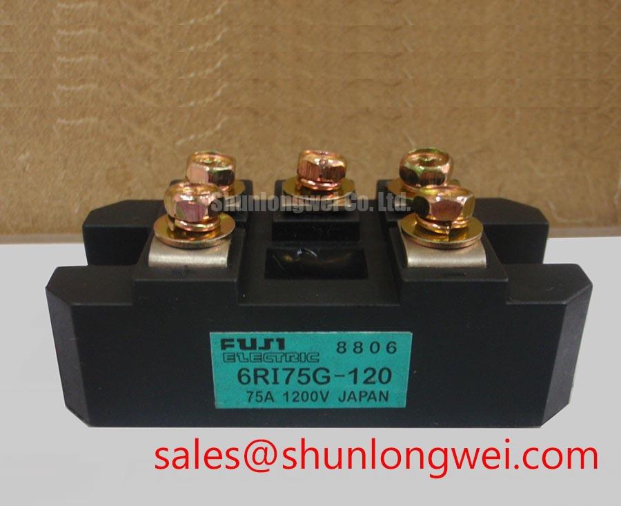
For systems operating on lower AC distribution levels (such as 380V–480V mains) where lower forward blocking margins are standard, engineers often evaluate complementary configurations such as the 2DI75M-120 power block. In 690V systems, however, the 1600V rating of the 6RI75G-160B provides the necessary insulation margin. Connecting an RC snubber network directly across the AC input terminals damps excessive transient voltage rates, absorbing high-frequency oscillations before they impact the internal junctions.
Reverse Recovery Charge Temperature Coefficient and Dynamic Snubber Energy Dumping
During commutation in high-voltage static switching banks, reverse recovery dynamics significantly affect turn-off losses and localized electromagnetic interference (EMI). The 6RI75G-160B features a maximum forward voltage drop of 3.5V at an operating current of 75A (Official Datasheet Specification). As junction temperatures increase toward maximum limits, reverse recovery charge typically expands, increasing peak reverse recovery current.
With an official maximum thermal resistance, junction-to-case, of 0.24 °C/W per element (Official Datasheet Specification) and a rated maximum power dissipation of 520W per element (Official Datasheet Specification), active heat removal determines dynamic reliability. Designers optimizing high-frequency discrete circuits alongside heavy modules can reference Fuji Electric High-Speed Discrete IGBTs for fast gate-drive timing architectures. The snubber circuit must absorb dynamic recovery energy without generating parasitic ringing across the laminated busbars.
Fuse Total Clearing I2t versus Device Melting Integral across 10ms Conduction Margins
Protection coordination is essential to prevent module case rupture during unexpected dead-short conditions. The continuous rated current of the 6RI75G-160B is 75A at a case temperature of 80°C (Official Datasheet Specification). To ensure short-circuit survivability, high-speed semiconductor fuses must be installed in series with each phase arm.
A safe protection scheme requires the total clearing energy rating of the fast-acting semiconductor fuse to remain strictly below the module's 10ms half-sine melting limit under all operating conditions. When selecting replacement parts during maintenance shutdowns, verify that the fuse clearing curve isolates the branch before silicon melting can lead to housing rupture. For detailed bench diagnostics and post-fault evaluation procedures, consult the testing guidelines outlined in the Field Engineer’s Handbook.
| Parameter | Official Datasheet Value | Engineering Significance |
|---|---|---|
| Max Voltage (VCES / VRRM) | 1600V | Ensures voltage margin for 575V/690V industrial AC grid applications. |
| Continuous Current (IC / IO @ TC=80°C) | 75A | Delivers steady-state capacity for medium-power switching and SVC banks. |
| Forward Saturation Voltage (VCE(sat) @ 75A) | 3.5V (Max) | Governs primary conduction dissipation during high-load switching stages. |
| Max Power Dissipation (PC per element) | 520W | Defines peak heat dissipation requirements for proper heatsink dimensioning. |
| Thermal Resistance (Rth(j-c) per element) | 0.24 °C/W | Determines junction temperature rise relative to the baseplate baseline. |