
Content last revised on September 26, 2026
6RI75G-120 Operational Boundaries: Reverse Recovery and Temperature Evaluation
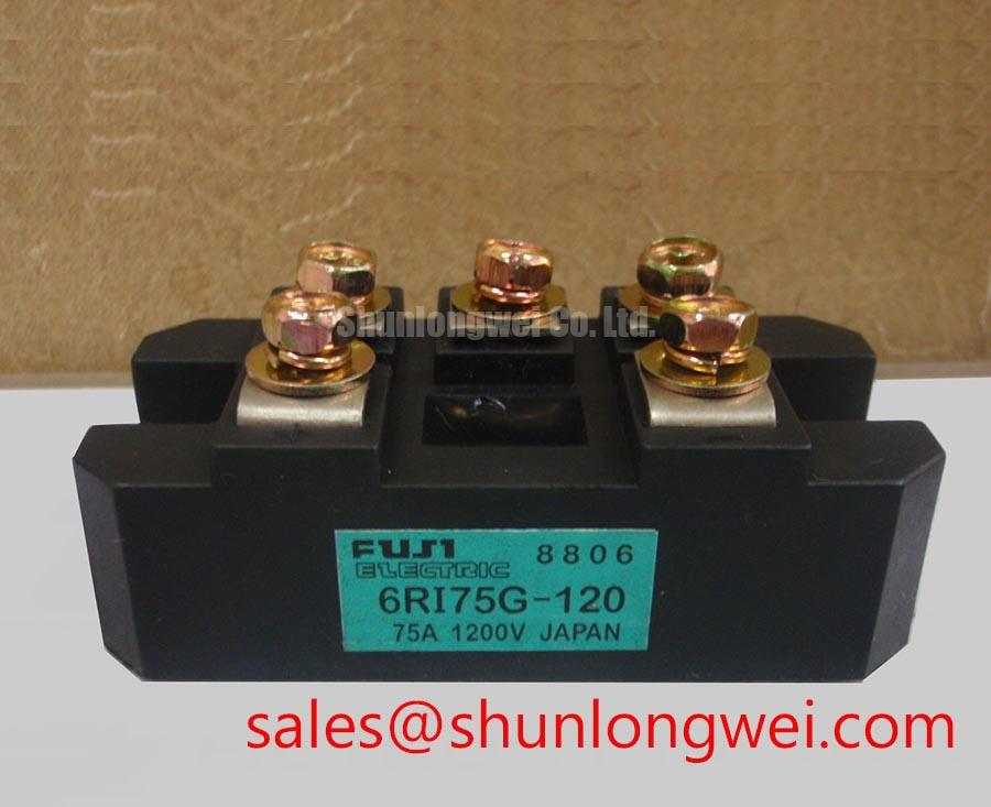
Begin a service check by isolating the rectifier from the power circuit, confirming the marked terminals against the equipment drawing, and measuring forward and reverse resistance with a suitable meter before applying operating voltage. The 6RI75G-120 is a Fuji Electric diode module intended for high power rectification duties, including evaluation in medium frequency induction melting and metal hardening power supplies.
| Parameter | Symbol | Test Condition | Official Rating |
|---|---|---|---|
| Repetitive peak reverse voltage | VRRM | Tj = −40°C to +150°C | 1200 V |
| Non-repetitive peak reverse voltage | VRSM | Sine wave, 10 ms | 1300 V |
| Average output rectified current | IO | Three-phase full wave, 50/60 Hz, TC = 93°C | 75 A |
| Surge forward current | IFSM | 10 ms half-sine, rated load initial condition | 750 A |
| Forward voltage drop | VFM | IFM = 75 A, Tj = 25°C | 1.25 V maximum |
| Reverse leakage current | IRRM | VR = VRRM, Tj = 150°C | 10 mA maximum |
| Thermal resistance | Rth(j-c) | Per diode chip, DC operation | 0.38°C/W |
| Operating junction temperature | Tj | Continuous operation | −40°C to +150°C |
| Dielectric isolation voltage | Visol | AC for 1 minute, terminals to baseplate | 2500 V |
The published ratings define the principal electrical boundary: repetitive reverse voltage is 1200 V, while the specified non-repetitive peak is 1300 V for a 10 ms sine-wave condition. These values should be checked against the measured commutation waveform in the induction power supply, especially where leakage inductance and high-frequency current transfer create reverse-voltage overshoot.
The supplied data does not state reverse-recovery charge, reverse-recovery time, peak reverse-recovery current, or a soft-recovery factor. Those characteristics must therefore be obtained from the applicable Fuji Electric technical documentation or verified with a controlled switching test. An oscilloscope with an appropriately rated differential probe can help compare commutation behavior, while a current probe can reveal recovery-current peaks and ringing. NIST resources can support measurement traceability and test-instrument verification, but they do not replace the component data sheet.
For service purchasing, the 2DI75M-120 may be evaluated as a related diode module only after confirming terminal arrangement, mechanical fit, thermal conditions, voltage ratings, and the equipment manufacturer’s approved parts list. Compatibility should not be inferred from current rating alone.
Preventing Spurious Faults: Pulse Transformer and Firing Circuit Relevance
The 6RI75G-120 is specified as a diode module, so it has no gate terminal, gate trigger current, gate pulse rise-time requirement, or back-porch holding current. A pulse-transformer firing circuit belongs to a controlled rectifier or thyristor stage, not to this diode device. If a replacement procedure refers to firing pulses, confirm that the circuit contains a separate controlled semiconductor before changing the rectifier assembly.
In a medium-frequency induction furnace, the practical interface is the power path: terminal identification, busbar polarity, commutation loop geometry, cooling interface, and protection coordination. Keep high-current paths short and symmetrical where the mechanical design permits, then verify switching-node voltage and current under the real load. The 2DI75A-140 can be reviewed as a related front-end or complementary topology device, subject to independent electrical and mechanical verification.
Pro Tip: De-energize and discharge the power stage before removing terminals or probes, and confirm the absence of stored energy with an appropriate measurement procedure.
Assembly Integrity and Layout Architecture for Surge Protection
The module’s official isolation rating is 2500 V AC for one minute between terminals and baseplate. This is an isolation test rating, not a complete system insulation or EMC certification. The enclosure, creepage and clearance design, bonding method, contamination level, and protective-earth arrangement remain system responsibilities.
AC input surge and overcurrent protection using MOVs, RC networks, semiconductor fuses, or other protective components should be selected from the measured supply system, prospective fault current, repetitive surge environment, and coordination study. IEEE 61000-4-5 testing may be relevant to the finished equipment, but the diode module itself should not be described as independently compliant with that system-level immunity standard. Verify the suppression network by observing the voltage directly at the rectifier terminals during representative surge and commutation tests.
Long conductors can increase parasitic inductance and encourage ringing. A design consideration is to minimize the high-current commutation loop and separate measurement wiring from power conductors. The control HMI resolution, whether VGA, SVGA, XGA, WXGA, FHD, or 4K, does not determine diode compatibility; display interface requirements should be checked separately using the applicable display resolution reference.
6RI75G-120 Thermal and Semiconductor Fuse Coordination
The official average output rectified current is 75 A under three-phase full-wave operation at 50/60 Hz with case temperature of 93°C. The stated surge forward current is 750 A for a 10 ms half-sine condition. These figures must not be treated as a complete short-circuit withstand specification. Fuse clearing energy, prospective fault current, bus impedance, pulse duration, and the manufacturer’s fuse coordination table are required for a valid protection assessment.
Because no fuse I²t coordination value is included in the supplied product data, the selected semiconductor fuse should be checked against the applicable Fuji Electric documentation and the measured fault study. Do not substitute the 750 A surge figure for a fuse-clearing limit. A controlled test should inspect fuse operation, terminal heating, insulation condition, and post-event diode leakage before returning the equipment to service.
Thermal evaluation should use the specified 0.38°C/W junction-to-case thermal resistance per diode chip together with the actual mounting surface, interface material, cooling arrangement, duty cycle, and case-temperature measurement location. The continuous junction-temperature range is −40°C to +150°C. The Ultimate IGBT Knowledge Base provides broader power-semiconductor design context, while the final thermal and protection validation must remain specific to the rectifier assembly and its operating waveform.