
Content last revised on October 28, 2026
Assembly Integrity & Layout Architecture: Thermal Interface Thickness Uniformity for SKKE
I inspect the heatsink contact surface and the previous thermal interface imprint before fitting an SKKE module, looking for uneven coverage, contamination, and evidence that the mounting faces did not seat evenly. These observations help separate a cooling interface problem from an electrical loading problem without treating either as the automatic explanation for overheating.
The supplied Official Specification gives junction-to-case thermal resistance, Rth(j-c), as 0.18 K/W. This describes the thermal path inside the module; it does not include the interface material or heatsink. As a Design Consideration, assess those additional thermal paths separately when evaluating case temperature under load. A clean heatsink can still perform poorly if the mounting interface contains voids or the cooling air bypasses its fins.
For thermal interface material application, my Engineering Recommendation is to use a controlled spreading or printing method matched to the approved material and mounting instructions. Check coverage rather than assuming that a visibly thick layer improves heat transfer. Excess material can increase interface resistance, while incomplete coverage can create localized hot regions. Check baseplate and heatsink flatness against their respective assembly requirements; do not attempt to correct excessive curvature by adding paste or tightening individual fasteners harder.
Progressive tightening in the specified sequence helps seat the assembly evenly. Mounting fasteners and electrical terminals need their own documented tightening requirements, suitable tools, and maintenance records. Keep busbars mechanically supported so that terminal alignment does not depend on pulling the module into position. Clearance around live conductors must follow the equipment insulation design, not an assumed spacing inferred from the module housing.
Maintenance Note: Trend terminal and case temperatures under comparable load conditions, and inspect cooling passages before changing the maintenance interval. Inspect thermal interface condition during planned removal rather than repeatedly disturbing an otherwise stable assembly. Where cold equipment enters warmer, humid surroundings, the maintenance procedure should address condensation before energization.
Transient Dynamics & Electrical Design: Fault-Clearing Boundaries for SKKE
Separate the diode current path from the controlled switching devices on the schematic before reviewing fault protection. SKKE is a diode module, not an IGBT module; gate-drive desaturation detection, Type-I and Type-II IGBT short-circuit behavior, and staged gate turn-off belong to the associated switching stage. They must not be presented as SKKE protection features or as evidence of a diode short-circuit withstand interval.
The supplied Official Specification states a surge forward current, I_FSM, of 4700 A at 10 ms and 25°C. That conditional surge rating is not a repetitive operating current or a universal protection-clearing allowance. As a Design Consideration, evaluate the protective device’s let-through behavior against the applicable semiconductor surge limits, initial temperature, fault waveform, and circuit impedance. A protective device’s nominal current alone does not establish coordination.
The average forward current rating, I_FAV, is 160 A at a case temperature of 100°C, while the specified forward voltage, V_F, is 1.55 V at a forward current of 500 A, both Official Specifications. These are different test conditions, not a single continuous operating point. Thermal assessment should use the actual conduction waveform and temperature-dependent loss information rather than multiplying unrelated headline values.
When evaluating integration into a heavy-duty variable-frequency AC motor drive, establish whether the module occupies the intended rectifier position and whether its complete terminal arrangement matches the circuit. Increasing inverter switching frequency can change system losses and cooling demand, but it does not create a universal SKKE derating schedule. Check case temperature with the cabinet closed, filters fitted, and the intended airflow established.
As an Engineering Recommendation, review neighboring gate-driver protection independently: desaturation blanking, soft turn-off, dead time, bootstrap supply behavior, and isolator common-mode transient immunity must suit those controlled devices. Unexpected trips should be correlated with measured power and control waveforms rather than corrected by extending protection delays without evidence.
Assembly Integrity & Layout Architecture: Overvoltage Trip Prevention Around SKKE
Trace the DC-link energy path before attributing a deceleration overvoltage trip to the rectifier module. A braking switch and resistor, when included in the equipment, perform a different function from the SKKE diode path. Their presence, connection, and control strategy must be established from the actual schematic rather than inferred from the module rating.
The supplied Official Specification identifies maximum repetitive peak reverse voltage, V_RRM, as 800 V. As a Design Consideration, compare the reverse voltage actually appearing across each diode path with its applicable operating boundaries, including switching excursions. A DC-link measurement at a remote test point can miss local peaks created by connection inductance and current commutation.
Braking resistor selection belongs to the system energy assessment. Designers should evaluate mechanical energy returned during deceleration, braking repetition, resistor pulse capability, continuous dissipation, and the braking switch’s operating limits. The trip threshold and switching strategy are equipment-level decisions. Neither can be derived solely from SKKE forward current or reverse voltage ratings.
During maintenance, inspect braking connections, heat-discolored terminals, resistor ventilation, and control-enable signals before altering acceleration or deceleration settings. Compare bus voltage with braking command and current to determine whether energy absorption occurs when expected. Where remote motor connections are involved, assess motor-terminal reflected-wave stress separately; it is not established by measuring only the rectifier terminals.
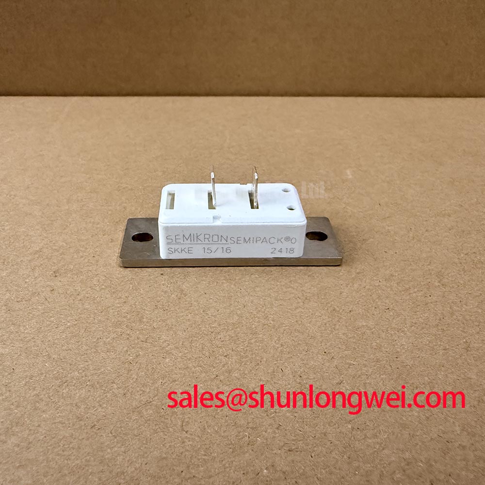
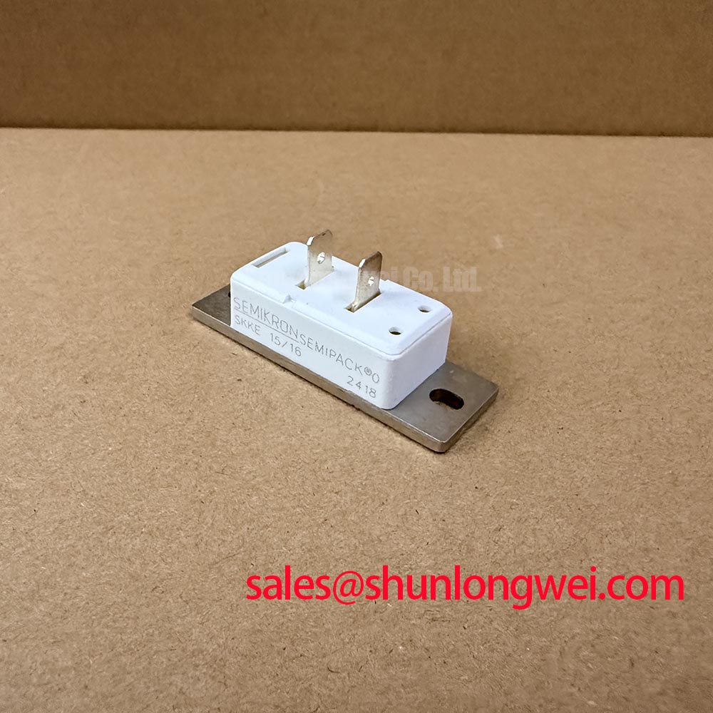
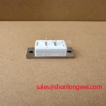
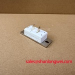
For replacement planning, retain the complete marking and mechanical drawing associated with the SKKE product reference. The separately listed SKKQ1500/18E is a comparison reference, not an established interchangeable replacement. Circuit configuration, semiconductor function, terminal assignment, mounting geometry, and thermal requirements must agree before any substitution is approved.
The supplied Official Specification also gives an isolation voltage of 3600 V AC for 1 minute. That test condition must remain distinct from allowable continuous working voltage and from the insulation performance of the complete installed assembly.
Preventing Spurious Faults: Diode Recovery and System Damping Around SKKE
Capture the diode-path voltage and commutating current together when investigating ringing, allowing for probe bandwidth, reference placement, and measurement-loop pickup. A sharp waveform feature can reflect circuit behavior or the measurement arrangement, so compare repeatable traces before changing components.
As a Design Consideration, reverse recovery depends on operating current, junction temperature, commutation conditions, and the diode’s characteristics. General background on carrier lifetime and recombination explains the role of stored carriers, but it does not establish a model-specific recovery current or softness factor. Do not assume that the SKKE rectifier is suitable for an inverter’s antiparallel freewheeling position merely because its voltage and current ratings appear adequate.
If measurements establish a need for damping, engineers should assess an RC snubber against the observed oscillation, repetitive energy, resistor heating, and capacitor stress. Adjusting turn-on gate resistance applies to the associated controlled switch, not to SKKE itself. Changes should be checked for their effects on switching loss, voltage excursions, and protection behavior. The discussion in Mastering Power System Dynamics provides supporting context for parasitic inductance and snubber evaluation.
Package technology also affects thermal interpretation. Semikron Sintering Technology describes a manufacturer packaging approach; it is not evidence that this SKKE module incorporates that construction. Keep maintenance decisions tied to measured case temperature, interface condition, and the specified thermal resistance.
After a wiring or damping change, repeat the same operating transition with comparable load and temperature. Record diode voltage, current, case temperature, and protection status together so that reduced ringing is not mistaken for an acceptable result if heating or fault behavior has deteriorated.