Content last revised on October 2, 2026
SKM120B020 Voltage Headroom and Transient Stress
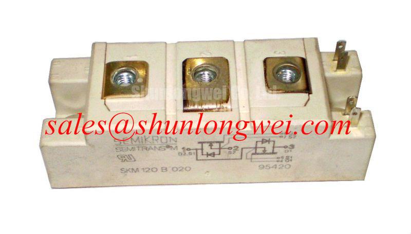
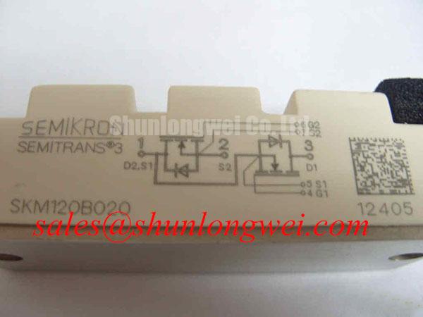
With the DC link discharged and isolated, compare the cold terminal measurements of the installed SKM120B020 against the equipment schematic before removing its busbar connections. This Semikron IGBT module has a stated 120.0 A rated current and Semitrans package (Official Specification). Its voltage rating is described in the supplied product information only as “Standard Industrial Rating”; that phrase is not a voltage value. Obtain the exact voltage rating and its test conditions from the applicable manufacturer documentation before approving a replacement or setting a DC-link limit.
Start the electrical assessment at the module terminals, not at the DC-link display. During turn-off, current flowing through busbar and connection inductance can raise the terminal voltage above the measured link voltage. As a Design Consideration, keep the commutation path compact and compare captured switching peaks with the confirmed device rating under the equipment’s relevant load and temperature conditions. Gate-drive changes should be assessed alongside that measurement because faster switching can alter both overshoot and losses.
Altitude and terrestrial radiation are sometimes raised during voltage-derating reviews, but the information available here does not establish an SKM120B020 single-event burnout rate, FIT value, or altitude derating curve. Do not turn those concerns into a numerical service-life prediction. For equipment operating beyond its original installation conditions, document the operating envelope and seek applicable manufacturer guidance. The broader Industrial Applications discussion can help frame system-level checks; it does not replace this module’s rating data.
When evaluating another module, including SKM75GB07E3, compare the original schematic, voltage and current ratings, terminal arrangement, gate-drive requirements, cooling interface, and mechanical fit. A similar product name or package family alone does not establish interchangeability.
Motor-Lead Reflections and Fault Coordination
At a motor connected by a long cable, a steep inverter output edge can reflect at an impedance discontinuity and increase the voltage seen at the motor terminals. That motor-terminal event is distinct from the IGBT’s turn-off overshoot at the module. A Design Consideration is to measure both locations with suitable probes before deciding whether an output filter or choke is needed. Filter selection depends on cable construction and length, motor insulation, switching behavior, and the equipment manufacturer’s limits; it cannot be sized from the SKM120B020 current rating alone.
For a suspected power-stage fault, record the condition of the fuse and measure the isolated module terminals against the circuit diagram. A low-resistance reading may warrant further investigation, but it does not identify a cause by itself. Fuse coordination likewise requires the fuse time-current and clearing data, the DC-link fault capability, and the IGBT’s applicable short-circuit limits. The supplied product information contains no SKM120B020 surge or short-circuit value with which to claim a verified clearing margin.
If the schematic includes a freewheeling diode, its reverse-recovery behavior belongs in the switching and noise review: recovery current can affect commutation stress and measured emissions. Confirm the actual circuit configuration and diode data rather than attributing a particular recovery characteristic to this module. Semikron-Danfoss describes the SEMITRANS industry-standard IGBT family, but family information should not be treated as an unverified SKM120B020 parameter.
Overvoltage Trips During Deceleration
On a traction drive being assessed for an electric forklift or material-handling vehicle, an overvoltage trip during deceleration calls for a sequence of measurements: confirm the DC-link waveform, the commanded braking state, and the condition of the equipment’s energy-absorption path. This is a potential integration example, not a claim that the SKM120B020 was specified for that vehicle. The schematic must establish whether braking uses a separate switch and resistor, another energy path, or a different control arrangement; the module designation does not confirm an internal braking IGBT.
Where a braking resistor is present, check its connection and control response before considering a change in component size. Its energy and thermal requirements depend on the load’s deceleration duty and the permitted DC-link excursion, so the system designer must determine them from the complete drive. If desaturation protection is present, compare its detection and shutdown waveforms with the gate-driver documentation. Neither a trip indication nor a measured collector-emitter voltage alone proves that the IGBT failed.
Gate-Drive Loop Geometry and Bench Waveforms
Trace the driver’s gate and emitter-return connections on the original layout before moving leads or changing resistance. Shared impedance with the main current path can disturb the effective gate voltage during switching; the severity has to be established from measured waveforms. Do not assume the SKM120B020 provides an auxiliary Kelvin-emitter terminal without confirming its terminal diagram. Miller coupling, turn-off behavior, and any observed oscillation should be evaluated with probes connected at the relevant module and driver terminals.
Pro Tip: Keep the gate-drive return clear of the high-current commutation path where the confirmed terminal layout permits it, then verify the switching margin with measured waveforms. For a replacement installation, also confirm the heatsink interface and the manufacturer’s mounting instructions before applying thermal compound or tightening fasteners. Mounting torque and compound thickness are assembly-specific values, not specifications established by the supplied SKM120B020 information. In a battery charging or discharging stage, repeated heating should be reviewed against measured case temperatures and the actual duty cycle rather than assigned an unsupported lifetime estimate.