Content last revised on September 12, 2026
Interconnect Compression and Heat Seal Integrity
| Parameter | Factory Information |
|---|---|
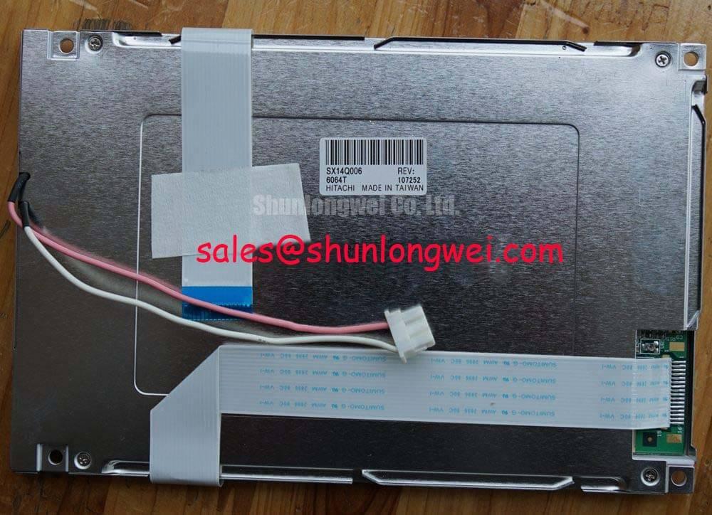
| Model | SX14Q006-C1 |
| Manufacturer | KOE / Hitachi |
| Product Category | Industrial Grade LCD/HMI Panel |
| Display Technology | FSTN / STN Monochrome Passive Matrix LCD Panel |
| Specification Status | Official Factory Spec Verified |
Inspect the display window for missing rows or columns, then measure connector continuity across the affected edge while comparing the result with a known good signal path.
The SX14Q006-C1 is identified as an FSTN / STN monochrome passive matrix LCD panel, so the first repair task is to separate a panel fault from an interconnect fault. A zebra strip, conductive elastomer, or heat seal connection can lose effective contact when the bezel shifts, the panel frame is distorted, or contamination forms at the contact interface. Row or column loss that changes when the bezel is gently supported should be treated as a mechanical contact symptom rather than evidence of a failed LCD cell.
Remove power before releasing the display assembly. Check whether the glass, bezel, connector frame, and cable remain parallel during reassembly. A tilted clamp can create uneven contact across the active area, producing intermittent characters, missing lines, or a contrast boundary that moves when the housing is handled. The correct mechanical condition is stable, even contact across the complete connector width; the final clamping arrangement must be determined by the original equipment construction and verified through vibration and thermal checks.
Use a lint-free swab and anhydrous IPA only where the equipment service procedure permits cleaning. Do not scrape exposed conductive surfaces or apply excessive force to the glass edge. Oxidation, adhesive residue, and dust can alter contact resistance, while aggressive cleaning can damage the seal or displace the elastomeric connector. After cleaning, inspect the contact path under magnification and repeat the continuity comparison with the panel disconnected from the host electronics.
Contrast problems require a separate electrical check. Confirm the bias rail, contrast control path, and reference return at the display connector with a properly rated instrument. Ripple or unstable bias can make text appear washed out even when the row and column connections are intact. The required bias voltage, polarity, filtering, and thermistor compensation must be taken from the original panel documentation and host circuit rather than inferred from the model name.
When a same-size service alternative is being evaluated, compare the glass outline, connector position, viewing area, pin assignment, and drive method before approving a substitution. The KCS057QV1AA-G01 may be reviewed as a separate sourcing option, but mechanical and electrical compatibility remain system-level verification tasks.
Cold-Start Response and Viscosity Damping in Sub-Zero Equipment
At cold start, record the time from display power application to stable readable characters while monitoring the logic supply and contrast bias for abnormal settling or interruption.
FSTN and STN liquid crystal panels can exhibit slower visual response at low temperature because the liquid crystal material changes its switching behavior as temperature falls. A delayed character transition does not automatically indicate a damaged panel. Compare the response with the host equipment’s normal cold-start sequence, and observe whether the delay affects the entire display or only selected rows and columns.
For telematics displays considered for heavy mining shovels or earthmoving equipment, the enclosure, heater strategy, front window, and vibration environment need evaluation together with the LCD. The SX14Q006-C1 is specified here as an industrial grade LCD/HMI panel, but the supplied factory information does not establish a complete system operating-temperature curve, shock rating, sealing level, or heater requirement. Those limits must be confirmed from the original equipment documentation before field integration.
Inspect the polarizer and front surface for yellowing, bubbling, edge lifting, scratches, or local whitening. Long exposure to ultraviolet radiation, heat, cleaning chemicals, and mechanical stress can alter optical performance in legacy terminals. A display that appears acceptable indoors may show reduced reflective contrast under direct sunlight or high ambient illumination. Test the panel with the original bezel, diffuser, window, and illumination arrangement because these parts influence perceived contrast.
Cold-start testing should include a stable supply measurement at the panel connector, a check for cable movement during enclosure contraction, and a visual record of the first readable frame. If the host uses a separate high-voltage backlight circuit, isolate that circuit during logic troubleshooting and follow the equipment service procedure for discharge and insulation verification. General high-voltage insulation behavior can be discussed using established partial-discharge principles; the partial discharge reference is background information rather than a product-specific certification for this LCD panel.
When the display is mounted behind a protective window, verify that the window does not press against the LCD face or bezel during cold contraction. Mechanical interference can resemble optical aging because it may produce local darkening, pressure marks, or intermittent contact. Designers should validate the complete assembly across the intended temperature range instead of assigning the panel a performance limit that is not stated in the factory data.
Backlight Strike and Inverter Fault Localization
Separate a dark image from a missing image by viewing the panel under controlled ambient light and checking whether characters become visible while the host is transmitting display data.
The supplied product information classifies the SX14Q006-C1 as an FSTN / STN monochrome passive matrix LCD panel, but it does not confirm a specific backlight technology, inverter arrangement, lamp voltage, lamp current, or connector pinout. Do not assume that a replacement panel uses the same backlight circuit as the removed unit. The system integrator should verify the required backlight type and supply conditions from the original panel documentation and the equipment schematic.
If a separate inverter is present, inspect its input supply, enable signal, return path, and output wiring before replacing the LCD. A failed inverter, open lamp circuit, poor connector contact, or protection shutdown can all create a dark screen while the LCD drive remains functional. Use an approved high-voltage probe and the equipment’s service method for any energized backlight measurement. Never use ordinary low-voltage test equipment on an unisolated high-voltage output.
When the image is visible only with external light, compare the backlight command waveform with a known-good unit and check whether the host controller is disabling the inverter because of an abnormal feedback condition. If the backlight starts and then stops, record the sequence rather than assigning a single cause. Tube aging, wiring insulation, transformer behavior, ballast switching, and protection feedback may require separate tests.
Clean gold-plated contacts only with a controlled process approved for the connector material. Anhydrous IPA may be suitable for removing light residue from compatible contacts, but the connector manufacturer’s restrictions and the host service procedure take priority. Confirm that the flex cable is fully inserted and that its locking mechanism is closed without twisting the cable. Repeated insertion can weaken the connector retainer or introduce alignment errors that appear as intermittent illumination or display faults.
For a panel replacement, compare the mounting apertures, viewing window, cable exit direction, connector orientation, and backlight clearance. The LM057QC1T08 can be reviewed as a separate display-system or peripheral sourcing reference, but it should not be treated as a confirmed electrical companion for the SX14Q006-C1 without a pin-by-pin and mechanical comparison.
⚡ Safety Interlock Note: Disconnect power and allow the inverter circuit to discharge before inserting or removing the LCD cable.
Logic Power and Liquid Crystal Bias Power-Up Coordination
Capture the logic supply, bias rail, frame signal, line pulse, and dot-clock activity during power-up and power-down to identify blanking, residual images, or an incorrect drive sequence.
Passive matrix LCD operation depends on coordinated addressing rather than a single image-data link. In a compatible host, frame synchronization, line pulses, and dot-clock activity must arrive with the expected polarity, timing relationship, and data format. The exact interface definition for the SX14Q006-C1 is not included in the supplied factory parameter set, so the original controller documentation and connector drawing must govern any signal assignment.
Power sequencing deserves the same attention. The host should establish the required logic conditions and bias state in the sequence specified for the original panel, then remove those conditions in a controlled order during shutdown. Applying a liquid crystal bias while control lines are undefined, or allowing a residual bias to remain after logic power has collapsed, can create white-screen behavior, ghosting, unstable contrast, or a retained image. These symptoms require waveform comparison at the panel connector rather than a single resistance measurement.
For a suspected white screen, verify that the panel return path is intact, the frame and line timing are present, and the contrast control responds without excessive ripple. For a residual image after power removal, observe how long the bias rail and signal lines remain active and check whether the host controller has a discharge path. The required supply voltage, bias polarity, timing limits, and shutdown order are system-defined unless explicitly stated in the original panel specification.
Long-term static interface content also deserves practical evaluation. A monochrome LCD may retain a visual impression when drive balance, contrast adjustment, temperature, or power sequencing is unsuitable. Rotate fixed diagnostic screens where the application permits, maintain balanced drive conditions, and verify contrast over the expected ambient range. This is a design consideration, not a guaranteed failure mechanism or a product-specific lifetime claim.
Flexible cables should be routed without sharp creases, tensile loading, or pressure from the rear cover. Check that the connector lock remains engaged after enclosure assembly and that the cable does not contact moving or vibrating hardware. During service validation, flex the harness only within the mechanical range allowed by the original equipment design while monitoring the display for transient row, column, or contrast changes.
For broader interface and integration context, engineers can consult The Ultimate Guide to Industrial TFT LCD Technology. It is a general technical reference and does not replace the original SX14Q006-C1 panel documentation, connector drawings, or host-controller timing requirements.