
Content last revised on September 18, 2026
Incoming Inspection and Identification
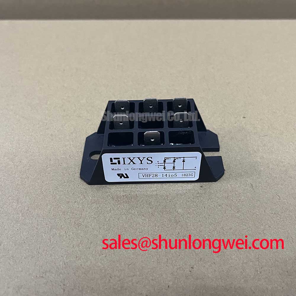
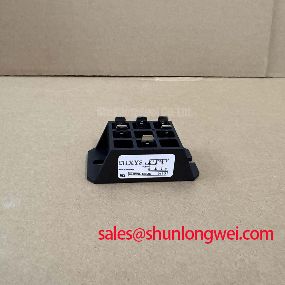
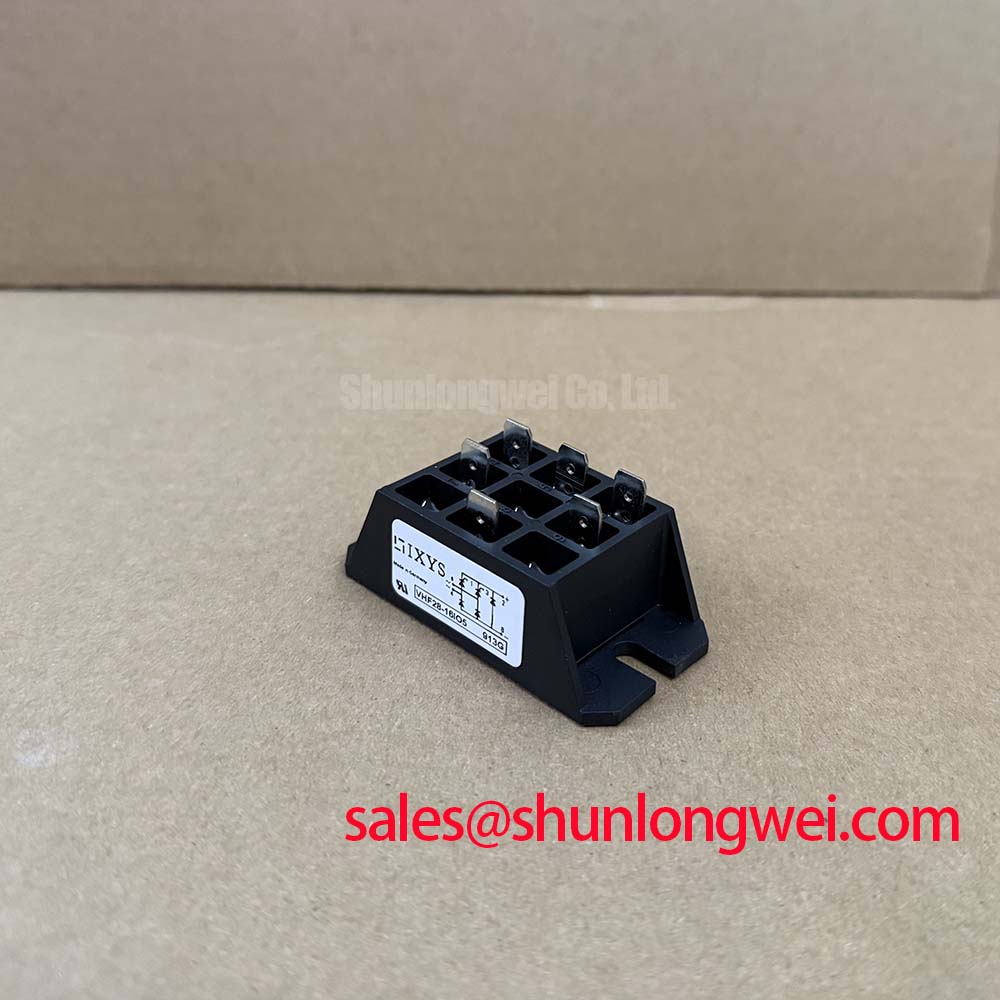
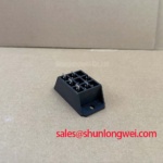
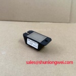
Begin incoming inspection with the power disconnected: verify the marking VHF28-16IO5, check the package for cracks or bent terminals, and confirm that the intended circuit position matches the original rectifier assembly before applying any test voltage.
The IXYS VHF28-16IO5 is a bridge rectifier module specified for high voltage industrial power conversion. Its published product data identifies a specified voltage rating of 1600.0 V, a specified current rating of 28.0 A, and a VUO/VUB Case. These are official product specifications. They should be checked against the equipment drawing, the original module marking, and the applicable operating conditions before a replacement is installed.
| Parameter | Official Specification |
|---|---|
| Manufacturer | IXYS |
| Part number | VHF28-16IO5 |
| Specified voltage rating | 1600.0 V |
| Specified current rating | 28.0 A |
| Package | VUO/VUB Case |
| Product category | Bridge Rectifier Module |
For bench work, use an isolated, current limited test arrangement and compare diode polarity with a known good unit or the equipment schematic. A multimeter diode test can help identify forward conduction paths, but the measured reading is a bench observation rather than an additional factory specification. If the result differs between corresponding paths, inspect terminal contact, contamination, wiring, and the surrounding circuit before assigning a device failure.
💡 Bench Tip: Use ESD precautions and record the cold state readings before energizing the assembly, because a cold reference is more useful than an isolated meter value when investigating an installed rectifier.
Field Diagnostics and Commissioning for Turn On Current Rise Limiting
During commissioning, first establish whether the VHF28-16IO5 is connected as the equipment designer intended. Confirm the AC input terminals, DC output terminals, polarity, conductor routing, and protective fuse arrangement against the original wiring documentation. The module’s 1600.0 V voltage rating and 28.0 A current rating define important device boundaries, but they do not by themselves establish the permissible surge current, fuse coordination, or load profile of a complete rectifier.
When the rectifier is connected to a large capacitive DC link, current rise during energization is determined by the source impedance, precharge arrangement, transformer characteristics, load capacitance, and protection circuit. An engineering recommendation is to verify the actual inrush waveform with a suitable current probe and to examine the DC bus rise during controlled commissioning. If an RC snubber or series saturable reactor is used, its selection remains system determined. Designers should verify its effect on voltage overshoot, repetitive stress, leakage current, and thermal loading rather than treating a generic component value as a VHF28-16IO5 specification.
Fuse selection also requires the manufacturer’s coordination data for the complete circuit. The semiconductor fuse’s total clearing I²t should be compared with the applicable withstand information for the rectifier and with the prospective fault current of the installation. No fuse I²t value is stated in the supplied product parameters, so it should be taken from the selected fuse manufacturer and checked against the relevant IXYS documentation. A fuse that interrupts quickly in one topology may not provide the same protection in another because wiring impedance, source power, and fault position change the current path.
For field replacement, the neutral option is to compare the installed electrical function, package geometry, terminal arrangement, and thermal interface with the original assembly. Engineers evaluating a related bridge rectifier can review SKD 25/14 as a separate device record, but final interchangeability must be confirmed from the equipment documentation and the respective datasheets.
Transient Dynamics and Mechanical Mounting Torque Sequence
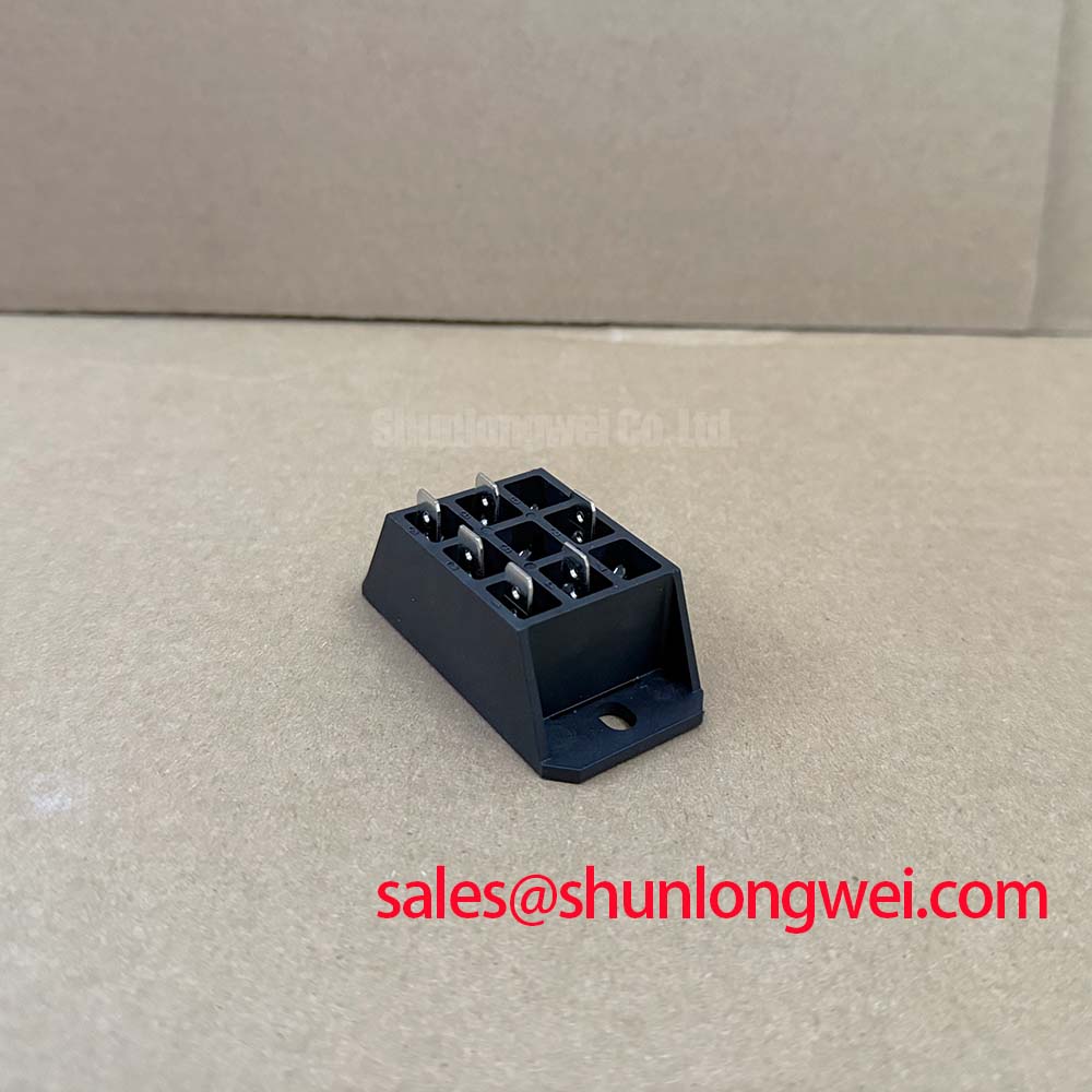
After electrical identification, inspect the mounting surface and terminal hardware before tightening anything. The VUO/VUB Case is a mechanical package designation, not a guarantee that every heatsink, clamp, washer, or terminal arrangement will be interchangeable. Confirm the original mechanical drawing, baseplate contact area, insulation requirements, and hardware sequence. The supplied official data does not provide a mounting torque value, so the correct torque must be taken from the applicable IXYS mechanical specification or equipment assembly instruction.
Uniform thermal contact is a design consideration during installation. The heatsink should be clean, flat within the limits specified by the system documentation, and free from particles that could tilt the module. Thermal interface material should be applied according to the material supplier’s instructions and the original assembly process. Excess compound can migrate toward terminals, while insufficient coverage can leave local air gaps. The practical acceptance method is to verify mounting flatness, hardware seating, and temperature behavior during a controlled load test.
⚠️ Field Alert: Do not apply a guessed tightening torque to the module or disturb its terminals while the DC link or auxiliary control circuits remain energized.
Transient performance is also affected by the physical loop formed by the transformer, rectifier, DC link, and protection network. Minimize unnecessary conductor length and loop area to reduce parasitic inductive overshoot, then verify peak voltage with an appropriately rated differential probe during switching and turn off events. A MOV may be evaluated as part of the overvoltage protection network, but its clamping level, energy capability, repetition rate, and failure mode must be selected for the system transient rather than inferred from the VHF28-16IO5 current and voltage ratings.
High voltage layout requires the integrator to check terminal creepage, electrical clearance, contamination level, enclosure conditions, and the applicable safety standard. These insulation distances are not stated in the supplied product parameters. The equipment designer should therefore use the original insulation coordination study and verify the finished assembly under the intended environment. A component’s voltage rating must not be presented as independent proof of complete equipment insulation compliance.
VHF28-16IO5 Thermal Electrical Optimization and Reverse Recovery Evaluation
In a bridge rectifier, commutation behavior depends on the external transformer leakage, line impedance, current waveform, temperature, and the characteristics of the individual rectifying junctions. Reverse recovery charge, reverse recovery time, peak recovery current, and recovery softness should be obtained from the applicable device documentation or measured under a defined test circuit. They are not included in the official parameters supplied for this product page, so no numeric recovery limit should be assigned to the VHF28-16IO5 here.
When a high current DC rectifier is evaluated for a green hydrogen electrolyzer power supply, the relevant measurement is the complete commutation waveform. Use isolated voltage measurement and a suitable current probe to observe the recovery current, transformer ringing, DC output disturbance, and any repeated overvoltage at the rectifier terminals. Compare the result with the known good power stage and with the semiconductor fuse and surge protection coordination. If a change in diode recovery behavior is suspected, check temperature and line conditions first because a waveform difference can also arise from the transformer, wiring, probe placement, or load control.
EMI should be treated as a system characteristic. The VHF28-16IO5 cannot independently claim compliance with a complete equipment EMC standard. Designers can review the general principles described in Electromagnetic Compatibility in Power Electronics and then verify conducted and radiated emissions at the assembled converter. Snubber networks, MOVs, cable routing, common mode impedance, and enclosure bonding should be tuned from measured waveforms and the applicable compliance plan.
Where the rectifier is part of a controlled solid state switching or bypass arrangement, the switching device and its control circuit must be evaluated separately from the bridge module. The basic operating context can be reviewed through Solid State Relay Working Principles, while the actual gate, trigger, isolation, and commutation requirements remain dependent on the selected circuit. The VHF28-16IO5 page does not establish a gate bias, trigger current, or negative cutoff voltage for any external switching device.
VHF28-16IO5 Operational Boundaries and Fuse I²t Coordination
Dead short protection should be assessed before the rectifier is returned to service. Record the upstream transformer rating, feeder impedance, fuse class, fuse manufacturer’s total clearing I²t, and the fault location. Then compare those conditions with the semiconductor withstand data applicable to the exact IXYS device revision. The supplied product information confirms the 1600.0 V and 28.0 A ratings, but it does not provide a fuse I²t coordination table or a guaranteed short circuit survival value.
An engineering calculation may be used to compare the clearing energy supplied by the fuse with the permitted semiconductor fault withstand, but the calculation is valid only when the current waveform, clearing time, prospective fault current, and device data come from identified sources. Avoid using a nominal fuse label as proof of protection. The clearing characteristic can vary with fault current and ambient conditions, and the wiring between the fuse and bridge can alter the stress seen by the device.
Inspect the rectifier after any protective operation. Check terminal discoloration, package deformation, insulation condition, heat spreader contact, and the cold diode paths with the circuit fully isolated. A changed diode test reading is an indication for further investigation, not a standalone failure classification. If the module is replaced, verify the cause of the protective operation before reapplying full energy, including precharge behavior, transformer waveform, DC link capacitance, and load-side faults.
For broader selection work involving voltage margin, current duty, cooling, protection, and circuit topology, the Power Semiconductor Selection Guide provides a useful engineering reference. A system integrator considering the VHF28-16IO5 for a high current green hydrogen electrolyzer DC power rectifier should validate the complete assembly through controlled voltage, current, thermal, insulation, and EMC tests before production release.