

Content last revised on October 19, 2026
VS-GBPC2502A Operational Boundaries: Evaluating Diode Peak Reverse-Recovery Current and I²t Limits
- Disconnect the assembly, discharge stored energy, and identify the bridge terminals marked AC, positive, and negative before connecting a meter.
- Record diode mode readings for each accessible rectifying path, reversing the probes and keeping the component temperature consistent.
- Check the mounting surface, terminal condition, and clearance against the equipment drawing before removing the existing bridge.
- Match the complete VS-GBPC2502A designation to the purchasing record and verify the reverse voltage requirement against the manufacturer datasheet.
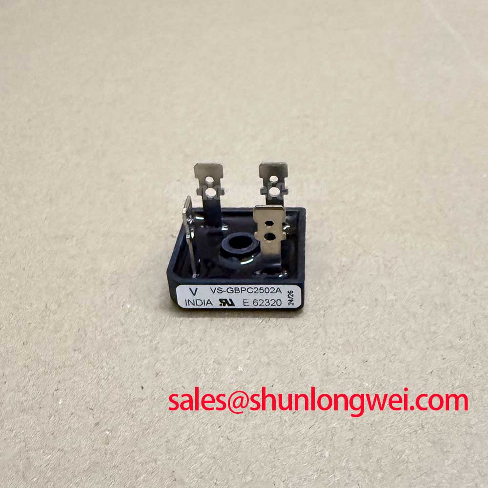
The Vishay VS-GBPC2502A is a diode bridge rectifier with a supplied current rating of 25.0 A and a Power Block / Bridge Case package description. Its rectifying function determines the relevant incoming inspection: terminal polarity, forward conduction, reverse blocking, and mounting compatibility. Gate drive measurements belong to other switching devices in the assembly.
| Identification or parameter | Value and specification status |
|---|---|
| Manufacturer and model | Vishay VS-GBPC2502A |
| Rated current | 25.0 A — Official Specification; apply the manufacturer’s stated thermal and loading conditions. |
| Package description | Power Block / Bridge Case |
| Reverse voltage, surge withstand, thermal limits, and mounting torque | Consult Datasheet for exact values and test conditions. |
Separate static diode screening from reverse recovery assessment: a handheld meter checks conduction direction but cannot establish peak reverse recovery current, recovery time, or recovery softness. These dynamic characteristics require a defined commutation circuit, controlled temperature, and suitable current and voltage measurements. Recovery time alone does not establish softness.
As a Design Consideration, compare the bridge’s response under the actual commutation conditions before associating a current spike with device deterioration. Probe placement, circuit inductance, and the load can influence the recorded waveform. Evaluate simultaneous current and voltage traces when investigating switching stress or interference; a diode mode result cannot predict those effects.
For static inspection, trace each AC terminal toward the positive output and trace the negative output toward each AC terminal using the manufacturer’s terminal diagram. Record both probe orientations. Similar readings across equivalent paths provide a useful comparison, while a discrepancy warrants isolation from parallel circuitry and repeat measurement. Meter readings depend on test current and temperature, so they should not be treated as datasheet forward voltage measurements.
💡 Bench Tip: Isolate the bridge from parallel current paths before comparing diode mode readings with a known good unit at the same temperature.
Keep device categories distinct during component evaluation: Vishay Siliconix Industrial Power MOSFETs provides information about controlled transistor devices, whose gate characteristics do not describe this diode bridge.
VS-GBPC2502A Thermal-Electrical Optimization: Dynamic Loading in Practical Applications
A diode bridge has no firing angle input; conduction follows the instantaneous source voltage and connected load. Applying a thyristor firing angle conversion curve to the VS-GBPC2502A would misrepresent its operation. Where an upstream controlled stage changes conduction timing, assess the resulting bridge current waveform and heating at the equipment level.
As a Design Consideration, distinguish average output current from pulsed charging current when evaluating thermal loading. A capacitor input circuit can concentrate conduction into short intervals. Review the manufacturer’s current rating conditions alongside the measured waveform, case temperature, and heat removal path before accepting operation at 25.0 A.
When assessing compatibility with a grid tied static var compensator or thyristor switched capacitor assembly, designers should verify whether this bridge belongs in an auxiliary rectifier circuit. Its designation does not establish suitability for the main compensation branch. The SKKT200-18E can be considered separately when reviewing a controlled rectifier stage, subject to its own circuit arrangement and ratings.
For replacement comparisons, the SKKH91-18E requires an independent topology, terminal, mechanical, and electrical assessment rather than selection by current rating alone. Where external current measurement is involved, fluxgate sensing principles explain magnetic field detection; that background does not specify the accuracy or bandwidth of a particular current transducer.
Assembly Integrity & Layout Architecture: Implementing I2t Sub-Cycle Melting Rating for VS-GBPC2502A
Compare semiconductor withstand with the fuse’s total clearing I²t under matching fault conditions, rather than using the fuse’s pre-arcing value alone. As a Design Consideration, coordination also depends on prospective fault current, circuit voltage, temperature, and the manufacturer’s stated pulse conditions. This comparison cannot establish a guarantee against package rupture.
Record the bridge withstand entry and its waveform conditions beside the selected fuse’s clearing data in the equipment protection worksheet. Check the fuse voltage rating, interrupting capability, and applicable manufacturer correction factors. Assess repetitive overload separately from a single non-repetitive surge event.
For assembly inspection, check base contact, mounting flatness, and terminal loading against the mechanical drawing. Apply the specified mounting torque for the actual package and fastener arrangement. When checking isolation, use the documented test points and procedure; a reverse blocking measurement between electrical terminals does not establish terminal to case insulation performance.
The Power Electronics Masterclass offers broader system reliability context. Keep the bridge acceptance record specific: polarity results, measurement conditions, mounting inspection, and the protection coordination reference used for the equipment.