

Content last revised on September 18, 2026
Field Diagnostics & Commissioning: Harmonic Current Injection and Line Filter in VUB71-16NO1 Topologies
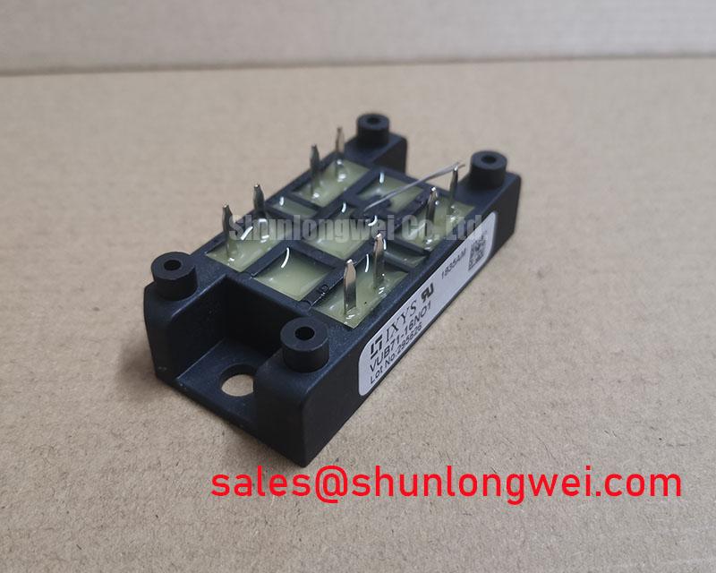
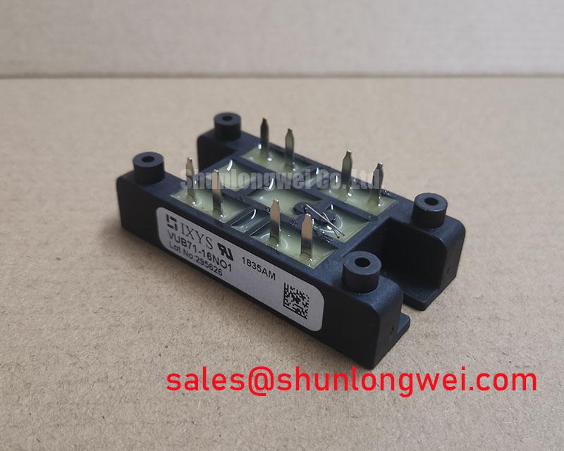
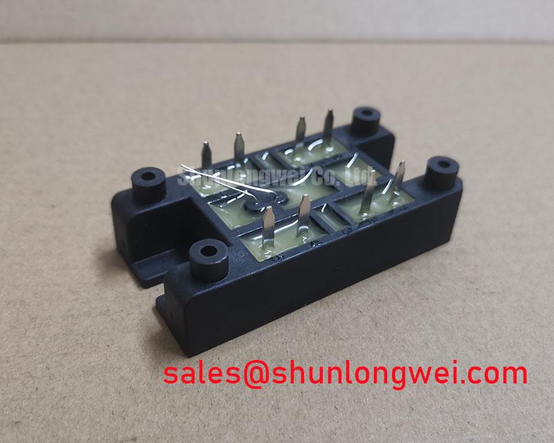
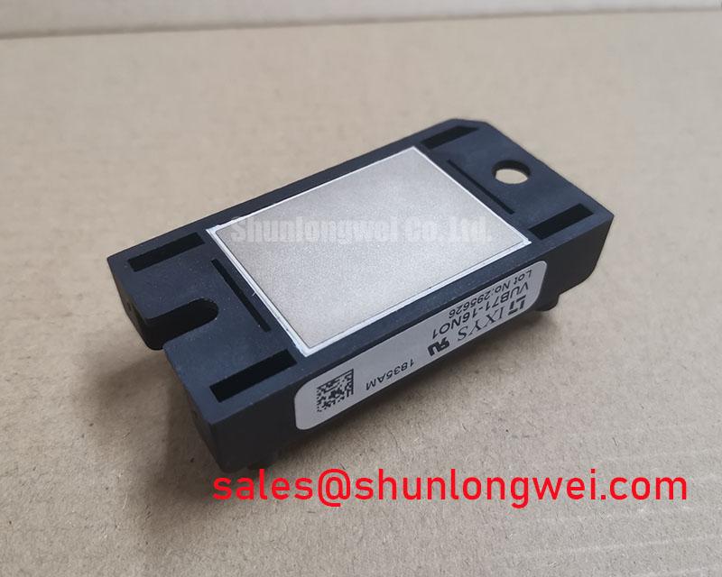
Begin incoming inspection by confirming the case marking against the required VUB71-16NO1 designation, then isolate the module from the surrounding power circuit before checking terminal to terminal diode conduction with a meter’s diode function. This IXYS bridge rectifier module carries an official rated voltage of 1600 V, an official rated current of 81 A, and the VUO/VUB Case housing. These three confirmed values establish the electrical and mechanical identity that must match the original service documentation before a replacement is considered.
For a cold static check, compare conduction direction and relative forward readings across the accessible power terminals with a known functional module or with the original equipment schematic. A meter result alone does not establish high current capability, reverse blocking performance, thermal condition, or dynamic recovery behavior. It does, however, help identify an obvious terminal short, an open current path, or a polarity mismatch before the module is returned to a live three phase assembly.
💡 Bench Tip: Keep the module and test leads protected against electrostatic discharge, and record cold readings under the same meter range when comparing a removed unit with a known good reference.
| Identification Item | Confirmed Value | Status |
|---|---|---|
| Manufacturer | IXYS | Product identification |
| Part number | VUB71-16NO1 | Product identification |
| Rated voltage | 1600 V | Official Specification |
| Rated current | 81 A | Official Specification |
| Case style | VUO/VUB Case | Official Specification |
| Product category | Bridge Rectifier Module | Product classification |
Before commissioning a high voltage three phase motor solid state soft starter, technicians should confirm whether the VUB71-16NO1 is installed as a line frequency rectification element, part of an auxiliary supply, or within a separately controlled power section. Its official 1600 V and 81 A ratings define the module’s published electrical boundary, but they do not by themselves identify the firing method, line impedance, capacitor bank, filter design, semiconductor fuse class, or control strategy used by the complete starter.
In an externally phase controlled AC to DC topology, firing angle has a direct effect on the average rectified output, input displacement, reactive demand, and harmonic content. As firing is delayed from near zero degrees toward 150 degrees, the controlled system can deliver less average DC output while drawing a more distorted line current. This description applies to the external conversion topology and its control devices. It must not be interpreted as an unverified claim that this specific IXYS bridge rectifier module contains controllable switching elements or supports a particular firing angle range.
During commissioning, measure line current on each phase and compare waveform shape, phase balance, and current timing against the original controller’s expected operating sequence. A current waveform with unexpected notches, asymmetry, or broad distortion can arise from several locations, including control timing, a weak line filter branch, incorrect phase connection, an upstream protective device, load conditions, or a power semiconductor fault. Measurements should be taken using equipment rated for the installation and correlated with a known healthy signal path rather than assigning one symptom to one component.
For fast current observation, a Rogowski coil can be useful because it senses changing current without a magnetic core saturation limitation associated with some conventional current transformers. The underlying measurement principle is described in this Rogowski coil reference. The system engineer should validate probe bandwidth, conductor placement, grounding arrangement, and scope setup before interpreting switching or commutation transients.
Line filter selection is a Design Consideration, not an official specification of VUB71-16NO1. The practical aim is to manage conducted disturbances and source impedance interactions without imposing unintended thermal or reactive loading on the supply. Check the filter wiring against the actual line and load configuration, verify earth continuity where applicable, and inspect terminals for heat discoloration, loosening, or movement. The module’s terminal layout and connection designations should be verified from the original equipment drawing or the applicable manufacturer documentation before any reconnect operation.
A controlled comparison with SKD 25/14 can be relevant only where the equipment documentation permits an engineering review of voltage class, current duty, circuit function, mounting interface, terminal arrangement, protection coordination, and thermal path. Equal looking housings or broadly similar voltage labels do not establish electrical interchangeability.
VUB71-16NO1 Operational Boundaries: Evaluating Fuse Total Clearing I2t versus Device Melt Limits
Dead short protection must be reviewed at assembly level. The confirmed ratings for VUB71-16NO1 are 1600 V and 81 A; no device specific surge current, fuse coordination value, internal melt limit, or allowable clearing I²t value is established by the supplied official product data. It would therefore be inaccurate to publish a fuse selection number or claim zero damage under a fault event for this module.
A semiconductor fuse coordination review normally compares the complete clearing I²t from the selected fuse documentation with the withstand capability stated for the protected semiconductor and with the prospective fault current available in the real installation. The review must include the operating voltage, supply source impedance, cable contribution, fault location, contactor arrangement, enclosure conditions, and the behavior of any parallel energy storage. These conditions are system determined and need validation from the fuse manufacturer’s curves, the equipment schematic, and the complete module datasheet.
For service work, first identify the installed fuse type and its exact position relative to the bridge module. Confirm whether the protective device is line side, DC side, or serving another branch. Inspect fuse holders, busbar interfaces, and cable terminations for evidence of heat stress or mechanical relaxation. A fuse can open because of a downstream fault, a transient event, a connection problem, or an upstream abnormality; fitting a replacement fuse without locating the initiating condition can leave the new bridge exposed to the same event.
Mounting pressure, heatsink flatness, thermal interface condition, and terminal tightness should also be examined when a bridge module is replaced. These are Design Considerations unless the applicable IXYS mechanical drawing specifies the required procedure. Use the manufacturer specified fastening hardware and torque where available, and verify that the module sits flat on the intended thermal surface without rocking or trapped debris. The original equipment documentation remains the controlling source for busbar orientation and terminal connection order.
The module’s voltage rating should be evaluated against measured and recorded system peaks rather than nominal line voltage alone. This is especially important where fault interruption, transformer leakage inductance, switching contactors, or commutation conditions can produce overshoot. Minimize parasitic loop inductance where the layout permits, suppress transients through the system protection network, and verify peak margins against the DC link and line conditions during controlled test work. For wider context on modular high power conversion evaluation, see The Race for Efficiency.
VUB71-16NO1 Thermal Electrical Optimization: IEC 61000-4-5 Industrial Surge Immunity: Practical Tuning
Surge immunity is a property of the assembled equipment rather than a certification that can be assigned to an individual bridge rectifier module. The commonly referenced industrial surge test family is IEC 61000-4-5. VUB71-16NO1 should not be described as independently compliant with an equipment EMC or surge standard solely from its 1600 V rated voltage. The system integrator should assess the complete line entry, protective earth arrangement, enclosure, cabling, filter network, control power section, and load.
In a motor soft starter, metal oxide varistors and RC suppression networks are often assessed as parts of a coordinated overvoltage strategy. This is an Engineering Recommendation: select components only after checking their continuous exposure, clamping behavior, pulse capability, temperature environment, line arrangement, and failure handling against the actual equipment requirements. An MOV that is poorly coordinated with an upstream fuse or thermal disconnect can create a different service risk, while an RC network that is not validated on the installed bus structure can alter dissipation or transient response.
Keep the protection path physically direct where practical, because conductor geometry affects the transient voltage seen at the protected circuit. Verify the final arrangement with suitably rated differential voltage measurement and current observation under controlled conditions. Do not infer surge performance from a static diode meter test. That test addresses only a limited cold state conduction check and cannot reproduce the energy, voltage rise rate, or thermal interaction present during a line surge.
Isolation boundaries around the soft starter gate drive and sensing circuits deserve the same disciplined inspection. Optical isolators and digital isolators can be exposed to common mode voltage movement created by the surrounding power circuit. Their capability, creepage arrangement, supply behavior, and controller grounding must be checked against their own manufacturer specifications. No common mode transient immunity value is supplied for VUB71-16NO1, so no such value should be attributed to the bridge module.
The physics of carrier mobility affects how semiconductor devices conduct and respond under electric fields, but it does not substitute for part specific switching data. Engineers seeking a general semiconductor background may consult this reference on electron mobility in semiconductor materials. For this IXYS module, dynamic claims should remain limited to values confirmed by the applicable product documentation and the installed circuit test results.
VUB71-16NO1 Operational Boundaries: Evaluating Diode Peak Reverse Recovery Current and S Limits
Reverse recovery evaluation requires device specific switching data, circuit current, commutation rate, temperature, stray inductance, and measurement bandwidth. The supplied official information confirms 1600 V, 81 A, and the VUO/VUB Case, but it does not confirm peak reverse recovery current, reverse recovery time, softness factor, stored charge, or a published switching loss value. Those parameters must not be estimated and presented as VUB71-16NO1 factory characteristics.
Where the module is used in a rectification path that experiences commutation, a sharp reverse recovery event can contribute to current spikes, voltage ringing, conducted interference, and thermal stress in the wider power loop. This is a Design Consideration. The appropriate response is to observe the actual circuit using correctly rated probes, compare the waveform with the original design expectations, and identify whether wiring layout, suppression parts, source impedance, controller sequencing, or the diode path requires further investigation.
Inspect the DC link capacitor branch, busbar joints, and snubber components before attributing ringing to the bridge module. A degraded capacitor connection or altered cable routing can change commutation behavior without a permanent static defect in the rectifier. Likewise, a passed static polarity test cannot verify recovery behavior under load. Service records should distinguish between confirmed measurements, component replacement history, and assumptions awaiting validation.
If an upstream rectification stage is being reviewed as part of the same repair, SKD82/18 is a related component reference for neutral comparison of documented circuit role and ratings. It should not be treated as an automatic substitute for VUB71-16NO1. Any compatibility decision requires confirmation of topology, voltage stress, current duty, mechanical fit, terminal definition, cooling arrangement, and protection coordination from the equipment documentation.
For final commissioning, energize only after terminal polarity, phase routing, protective earth connections, insulation clearances, cooling interfaces, and external protection devices have been checked against the original assembly record. Monitor the power section under controlled load conditions and investigate abnormal waveform shape, temperature rise, noise, or protective operation using measured evidence. This approach keeps the VUB71-16NO1 evaluation tied to its verified ratings and to the actual operating boundaries of the equipment.