

Content last revised on October 11, 2026
Preventing Spurious Faults: AC Input Transient Overvoltage Clamping Guidelines for VUO160-16NO7
Isolate the AC supply, verify that the DC link is discharged, and trace the rectifier connections before investigating repeated input protection trips around the VUO160-16NO7. Distinguish an upstream supply disturbance from a downstream short circuit before replacing the module; either condition can produce similar equipment symptoms.
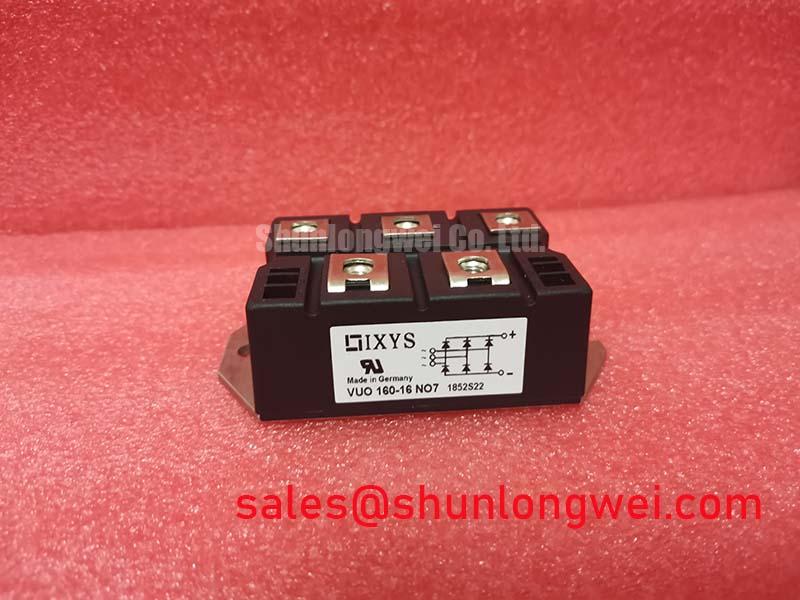
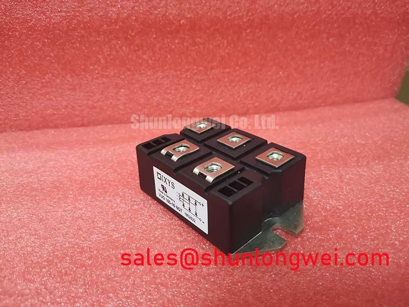
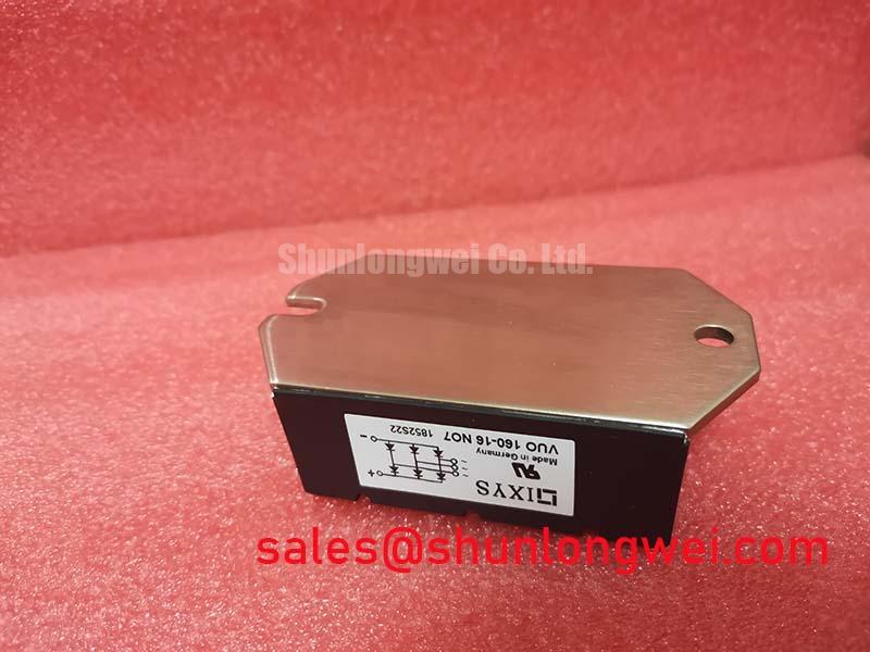
The IXYS VUO160-16NO7 is a Bridge Rectifier Module with a specified voltage rating of 1600 V and rated current of 160 A under the manufacturer's specified conditions. Consult the datasheet for the applicable rating conditions. It is a diode rectifier, not a gate-controlled thyristor module. That distinction determines which commissioning checks belong at its terminals and which belong elsewhere in the power circuit.
Inspect the AC input protection network for disconnected surge suppressors, deteriorated connections, and evidence of repeated thermal stress. As a Design Consideration, evaluate MOV protection against the actual supply configuration, maximum continuous voltage, prospective surge exposure, and upstream protective devices. Select clamping characteristics so the protected rectifier remains within its applicable electrical limits during the specified disturbance.
Surge immunity assessment uses IEC 61000-4-5. This is an equipment-level test framework, not evidence that the VUO160-16NO7 independently satisfies an immunity requirement. The system engineer should establish the applicable test conditions and assess voltage at the rectifier connections using appropriately rated measurement equipment.
Where an RC suppression network is present, inspect its components and wiring against the equipment schematic. Design Consideration: damping depends on the surrounding impedance and transient energy, so component selection should follow measured circuit behavior rather than a universal resistor or capacitor prescription. Keep protective connections electrically effective without compromising required clearances.
Trace the rectifier output to the DC link before evaluating surrounding modules. A separate rectifier such as MDS300A1600V belongs in an assessment of an additional rectification branch only when the equipment architecture requires it; it is not an assumed companion or interchangeable replacement. Check terminal functions against the connection drawing, not terminal position alone.
Field Diagnostics & Commissioning: Diode Conduction Checks in VUO160-16NO7 Topologies
The VUO160-16NO7 diode bridge does not require firing pulses, holding-current control, or a gate-current rise-time setting. If the equipment contains a separately controlled converter stage, troubleshoot that stage against its own component documentation rather than transferring thyristor requirements to this rectifier.
With the module safely isolated from parallel circuit paths, compare diode conduction behavior across corresponding connections using the manufacturer's circuit diagram. Engineering Recommendation: investigate inconsistent readings with a suitable instrument and a known-good reference, accounting for connected capacitors and other semiconductor paths. A single resistance or diode-test reading does not establish the cause of an operational trip.
Use the following comparison to organize replacement assessment, not to authorize substitution. Mechanical fit, circuit configuration, terminal arrangement, cooling requirements, and rating conditions remain part of the engineering decision.
| Assessment item | VUO160-16NO7 | VUO82-16NO7 reference |
|---|---|---|
| Manufacturer | IXYS | Consult Datasheet |
| Specified voltage rating | 1600 V | Consult Datasheet |
| Rated current under specified conditions | 160 A | Consult Datasheet |
| Package classification | Module | Consult Datasheet |
| Terminal layout, dimensions, mounting torque and rating conditions | Consult Datasheet | Consult Datasheet |
The VUO82-16NO7 provides a related part-number reference for comparison, not evidence of equivalent current capability. When evaluating a medium-frequency induction melting or hardening furnace input rectifier, designers should verify the bridge configuration, loading, mounting interface, and cooling arrangement against the original equipment requirements.
VUO160-16NO7 Operational Boundaries: Evaluating Short-Circuit Withstand and Coordination Limits
Compare the semiconductor fuse's total clearing I²t with the rectifier's applicable withstand data under compatible voltage, initial temperature, and fault conditions. Engineering Recommendation: review total clearing I²t rather than pre-arcing I²t alone, together with peak let-through current and the fuse's interrupting capability. The 160 A current rating is not a short-circuit protection specification.
Include DC-link capacitor discharge paths in the protection review because an upstream fuse does not necessarily interrupt every source of fault energy. Protection coordination aims to limit damage; it cannot justify a guarantee of damage-free behavior under every short circuit. Preserve the equipment manufacturer's protective topology unless an engineering reassessment supports a change.
During planned outages, inspect heatsink airflow, thermal-interface condition, and terminal discoloration. Engineering Recommendation: establish inspection intervals from operating conditions and observed temperature trends, and use the specified fastening procedure rather than generic torque values. The general mechanism described in thermal fatigue explains why repeated temperature changes matter, but does not establish a module-specific power-cycling lifetime or test standard.
Maintenance Note: Monitor terminal temperature trends and verify unobstructed cooling airflow during scheduled inspections.
If nearby switching stages are also under investigation, Wide Bandgap Revolution offers background on switching-device integration, not VUO160-16NO7 specifications. Keep switching-stage diagnostics separate from bridge checks, and address moisture or condensation before re-energizing affected connections.