



Content last revised on September 25, 2026
Transient Dynamics and Electrical Design: Power Factor and Harmonic Mitigation
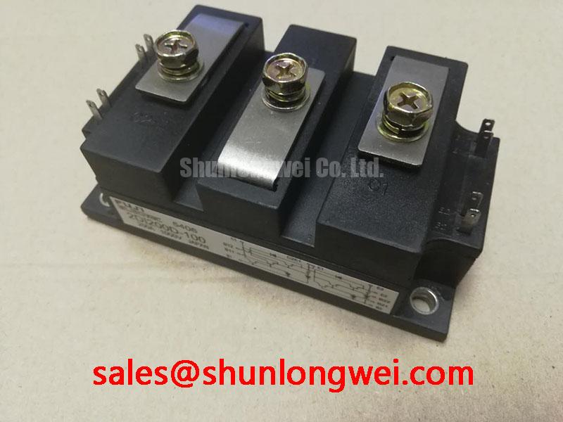
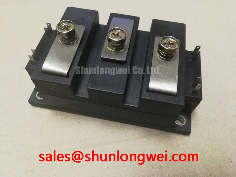
The 2DI200D-100 is a diode bridge module, so it does not provide controlled firing angle operation. Any firing-angle control belongs to an upstream thyristor or controlled rectifier stage, not to this diode module itself. When reviewing a furnace power supply, separate the uncontrolled diode conduction path from the controlled section before assessing displacement power factor, reactive power, or harmonic current.
A practical inspection should begin with the AC input and DC output connections shown in the equipment documentation. Confirm that each conductor is landed on the correct terminal, that cable insulation has not been heat damaged, and that the protection device is coordinated with the actual short circuit environment. The module’s 1000.0 V voltage rating and 200.0 A current rating are Official Specification values, not a complete system design limit. Peak repetitive voltage, overload duration, commutation conditions, heatsink temperature, and pulse current must be checked against the applicable Fuji Electric documentation.
Fuse selection should use the manufacturer’s published semiconductor fuse and I²t coordination data where available. Do not infer a permissible short circuit duration from the nominal current alone. During commissioning, waveform measurements on the AC input and DC link can help identify abnormal commutation spikes, phase imbalance, or harmonic conditions created by the surrounding converter.
Assembly Integrity and Layout Architecture: AC Input Transient Clamping
AC input protection for an induction heating supply should be reviewed as a complete network rather than as a property of the diode module. A design consideration is to place surge limiting, semiconductor fusing, and any RC damping network according to the equipment insulation system, prospective surge level, and switching arrangement. IEC 61000-4-5 test requirements may be relevant to system verification, but they do not establish a standalone compliance claim for this component.
When MOVs or snubbers are considered ahead of the rectifier, the system designer should verify their continuous voltage capability, surge energy, leakage, thermal behavior, and interaction with the upstream transformer and switching devices. Layout should minimize parasitic loop area to reduce transient overshoot, with final peak voltage margins verified during controlled switching tests. Terminal connections must follow the original equipment drawing; the available product information here does not define a universal terminal torque, fuse I²t value, or snubber component value.
For a rectifier topology requiring an associated high current device, engineers may also review the neutral product context of 2DI200A-050. It should be treated as a separate evaluation item, not an automatic substitute, until voltage, current, mechanical fit, thermal conditions, and circuit function are confirmed.
2DI200D-100 Operational Boundaries: Mechanical Mounting and Thermal Limits
Mounting condition directly affects the thermal path from the power semiconductor assembly to the heatsink. Before installation, clean both contact surfaces using an approved process, inspect for burrs or distortion, and apply the thermal interface material according to the original equipment service specification. The amount and type of compound are system dependent and should not be inferred from the 200 A nameplate value.
Use a crosswise tightening sequence where the mechanical design permits it, allowing the module base to seat evenly without twisting the housing. The manufacturer’s installation instructions should control bolt size, washer arrangement, torque, insulation requirements, and any permitted mounting orientation. During maintenance, inspect fan operation, heatsink fin blockage, duct condition, and evidence of thermal discoloration. A temperature trend taken at comparable load is more useful than a single unreferenced surface reading.
⚠️ Maintenance Note: Deenergize and isolate the equipment before touching power terminals, and periodically check heatsink cleanliness and contact temperature under a known operating load.
Transient thermal impedance and pulse peak junction temperature require the official device curves and the actual load waveform. If those curves are not available in the service file, the correct action is to obtain the applicable Fuji Electric documentation rather than estimate a junction temperature limit.
2DI200D-100 Operational Boundaries: Gate Trigger Dynamics
The 2DI200D-100 is a diode bridge module and has no gate trigger terminal. Requirements such as gate pulse rise time, gate current, holding current, multi pulse firing, or negative gate off bias apply to a separate thyristor or IGBT stage in the surrounding power converter. Applying those requirements directly to this diode module can lead to an incorrect wiring or replacement decision.
For a furnace controller that includes gated semiconductor devices upstream or downstream, verify the driver reference, isolation barrier, common mode behavior, and switching waveform independently. Oscilloscope measurements should be made against the known good signal path, with suitable high voltage probes and a defined grounding method. The engineering article Evolution of Negative Off Bias Gate Drive Circuits can provide background for systems that use negative gate bias, while the module itself remains a passive rectifier component.
Where the rectifier feeds a related conversion stage, the topology may also be reviewed alongside 2DI200MC-050 as a separate, objectively evaluated device. Confirm electrical ratings, mechanical dimensions, cooling interfaces, and the original schematic before considering any cross reference.