


Content last revised on April 16, 2026
Fuji Electric 1MBI300SA-120B: A Deep Dive into the 1200V 300A S-Series IGBT Module
Introduction and Core Specifications
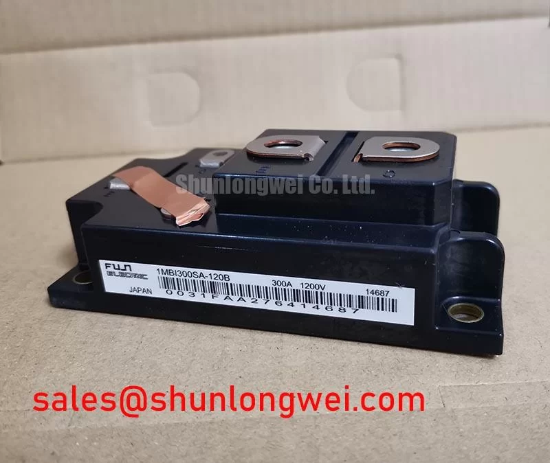
The Fuji Electric 1MBI300SA-120B is a 1200V, 300A single-pack S-Series IGBT Module engineered for exceptional thermal performance and reliability in demanding high-power applications. With its core specifications of 1200V | 300A | VCE(sat) 2.7V max, this module delivers robust power handling and efficient operation. Key engineering benefits include superior thermal stability and a high-reliability design for long service life. It directly addresses the challenge of managing heat in high-current industrial systems by providing a low thermal resistance path from the chip to the heatsink. For industrial drive systems requiring robust performance and dependable thermal management, this 300A module provides an optimal balance of power and reliability.
Application Scenarios & Value
System-Level Benefits in Industrial Power Conversion
The 1MBI300SA-120B is engineered for high-stress industrial environments where consistent performance is non-negotiable. Its primary value is demonstrated in applications such as high-power Variable Frequency Drives (VFDs), uninterruptible power supplies (UPS), and AC/DC servo drives. In a typical VFD controlling a heavy inductive motor load, the startup torque and dynamic load changes generate significant thermal stress. The engineering challenge is to dissipate this heat effectively to prevent junction temperature overshoots that degrade the component's lifespan. The 1MBI300SA-120B's low thermal resistance (Rth(j-c)) directly solves this problem by creating a highly efficient pathway for heat to escape, ensuring the IGBT operates within a safe temperature margin. What is the primary benefit of its low thermal resistance? Enhanced long-term reliability by maintaining lower operating temperatures under load. This robust thermal management capability translates into more reliable machinery, reduced downtime, and the potential for more compact system designs. For systems with even higher current demands, the related 1MBI400N-120 offers a 400A rating within a similar voltage class.
Key Parameter Overview
Decoding the Specs for Thermal Stability and Electrical Robustness
The technical specifications of the 1MBI300SA-120B underscore its suitability for high-power switching applications. Each parameter is a critical piece of the puzzle for system designers aiming for efficiency and reliability.
| Parameter | Value | Engineering Value & Interpretation |
|---|---|---|
| Collector-Emitter Voltage (Vces) | 1200V | Provides a substantial safety margin for applications operating on 400V to 575V AC lines, protecting against voltage spikes common in industrial environments. |
| Continuous Collector Current (Ic) | 300A (at Tc=80°C) | This high current rating confirms its capacity for heavy-duty applications like large motor drives and industrial inverters, ensuring performance without significant derating. |
| Collector-Emitter Saturation Voltage (VCE(sat)) | 2.1V (typ) / 2.7V (max) | Directly impacts conduction losses. The typical value of 2.1V at 300A indicates efficient power transfer, minimizing the heat generated during the on-state and improving overall system efficiency. |
| Thermal Resistance (Rth(j-c)) | 0.085 °C/W (IGBT) | This is the module's standout feature. A lower Rth(j-c) value is like having a wider pipe for heat to flow through; it ensures the heat generated at the silicon junction is evacuated efficiently to the heatsink, which is the cornerstone of thermal reliability. |
| Reverse Bias Safe Operating Area (RBSOA) | Square, up to 1200V | A wide, square RBSOA guarantees the module's robustness during turn-off, especially with inductive loads. It gives engineers confidence that the device can safely handle stressful switching events without failure. |
Download the 1MBI300SA-120B datasheet for detailed specifications and performance curves.
Frequently Asked Questions (FAQ)
How does the 0.085 °C/W thermal resistance of the 1MBI300SA-120B impact heatsink selection?
A lower thermal resistance value allows for more effective heat transfer. This means a smaller, more cost-effective heatsink may be used to maintain the same junction temperature compared to a module with higher resistance. Alternatively, it provides a greater thermal margin with a standard heatsink, enhancing system reliability, especially in high ambient temperature environments.
Is this module suitable for paralleling to achieve higher current output?
The datasheet provides characteristics for a single module. While paralleling IGBTs is a common practice, it requires careful engineering consideration. Designers must analyze the VCE(sat) distribution and gate threshold voltage to ensure proper current sharing. For guidance on this topic, it's recommended to consult application notes from the manufacturer, like Fuji Electric, on paralleling power modules.
What does the "S-Series" designation signify for this Fuji IGBT module?
The "S-Series" from Fuji Electric typically represents a generation of IGBTs focused on balancing performance and reliability for industrial applications. These modules are known for their robust design and proven performance in the field, making them a staple for systems where longevity and durability are paramount.
What is the significance of the square RBSOA for a motor drive application?
In a motor drive, the IGBT must turn off current flowing through the motor's inductive windings. This action can create a large voltage spike across the IGBT. A square Reverse Bias Safe Operating Area (RBSOA) indicates that the module can safely withstand high collector current and high collector-emitter voltage simultaneously during this stressful turn-off event, preventing component failure and enhancing the drive's overall robustness.
Can the 1MBI300SA-120B be used in high-frequency welding applications?
While the module is primarily designed for motor drives and UPS systems, its suitability for high-frequency welding depends on the specific switching frequency. Designers must carefully analyze the switching losses (Eon, Eoff) provided in the datasheet to calculate the total power dissipation at the target frequency. Exceeding the thermal dissipation capabilities will lead to overheating, so a thorough thermal simulation is essential. For more specialized high-frequency designs, resources like this guide on high-frequency IGBT selection can be insightful.
Technical Deep Dive
A Closer Look at the Thermal Path and Mechanical Design
The long-term reliability of a high-power module like the 1MBI300SA-120B is not just determined by its silicon; the mechanical and thermal design of its package is equally critical. The module's specified Rth(j-c) of 0.085 °C/W is the result of a meticulously engineered thermal stack. Think of it like the cooling system in a high-performance engine: every layer, from the IGBT chip itself to the Direct Bonded Copper (DBC) substrate and the copper baseplate, is optimized to minimize thermal impedance. This ensures that the waste heat—an inevitable byproduct of switching 300 amperes—has an unobstructed path away from the sensitive semiconductor junction. This efficient heat evacuation is fundamental to preventing thermal runaway and extending the power cycling capability of the module, directly contributing to a longer operational life in the field.
An Engineer's Perspective on the 1MBI300SA-120B
From a design engineer's viewpoint, the 1MBI300SA-120B is a workhorse component built on a foundation of thermal integrity. Its specifications are not about pushing the limits of switching speed but about delivering sustained, reliable power. The excellent thermal resistance and robust SOA provide tangible design margins, simplifying the thermal management strategy and instilling confidence in the system's ability to withstand the rigors of industrial operation. This module is less about bleeding-edge performance and more about providing a predictable, durable, and efficient core for high-power conversion systems where uptime and service life are the most valuable metrics.