


Content last revised on September 10, 2026
Eye Diagram Voltage Margin and Differential Noise Floor Verification in High Vibration Bays
For a railway passenger information system or cab signalling display, begin the electrical evaluation with the complete signal path rather than with the panel alone. Record the source controller, cable assembly, connector keying, shield termination, and receiver arrangement used by the original display. The product information supplied for the G150X1-L01 does not confirm a specific LVDS pin assignment, JEIDA or VESA data format, pixel clock range, or transmitter voltage window. These parameters should be taken from the original panel documentation or the system service manual.
When the display operates near variable frequency motor drives, traction converters, or other high energy switching equipment, a differential probe can be used to compare the known good signal path with the replacement installation. Observe the eye opening, common mode movement, clock quality, and data transitions at the panel connector under representative operating conditions. A reduced eye opening may indicate cable loss, impedance discontinuity, connector contamination, grounding interaction, or source timing variation. It should not be assigned to the G150X1-L01 alone without checking the complete interconnect.
A 360 degree shield connection around a suitable FFC or LVDS cable is a Design Consideration where the enclosure and cable construction support it. The objective is to control the return path and reduce coupling into the differential pair. The system designer should also assess whether common mode ferrite suppression is appropriate for the actual cable impedance and switching spectrum. Adding magnetic components without measuring their effect can increase insertion loss or alter the signal edge shape, so the result should be checked with the oscilloscope and the display’s image output.
Horizontal noise bands, intermittent pixel errors, or image instability can also be associated with supply ripple, poor reference bonding, connector movement, or timing incompatibility. Check the panel supply at the display connector during startup and during maximum backlight demand, while separately monitoring the controller supply. Verify the enable sequence and reset behavior against the original panel requirements. The correct supply voltage must not be inferred from the model number because it is not included in the supplied official parameters.
Low ambient temperature introduces another verification point. Liquid crystal response can become slower as temperature falls, and any heater strip or enclosure thermal control should be assessed as part of the system. Measure the time required for the image to reach stable contrast after startup, then compare it with the service requirement. This is a system observation, not a published G150X1-L01 response specification. Designers evaluating the module for outdoor control cabinets, railway passenger information terminals, or cab displays should validate the complete timing and environmental envelope before approval.
💡 Pro Tip: Keep the differential signal pair routing symmetrical and confirm the shield return path during vibration testing rather than relying only on a static bench image.
High Voltage Striking Potential and Secondary Coil Insulation Testing
The supplied factory information identifies the G150X1-L01 as a TFT LCD display module but does not confirm whether the specific unit uses a CCFL backlight, an LED backlight, a dedicated inverter, or an integrated driver. The system integrator should verify the required backlight technology from the original panel documentation. Do not connect a CCFL inverter or an LED constant current driver based solely on the panel model designation.
If the original assembly uses a high voltage CCFL circuit, the cold ignition event and secondary winding insulation belong to the inverter and lamp assembly evaluation. High voltage testing should be performed only with equipment and procedures suitable for the actual inverter design. The commonly encountered ignition range in a legacy CCFL system must not be treated as an official G150X1-L01 rating because no such value is provided in the supplied specification. Test personnel should isolate the display, follow the equipment manufacturer’s safety procedure, and confirm that the test does not apply unintended stress to the LCD electronics.
Inspect the inverter transformer, lamp wiring, insulation barriers, connector spacing, and chassis clearance for evidence of tracking, carbonization, or mechanical displacement. Acoustic buzz can result from magnetics, mounting resonance, drive frequency, or loose mechanical parts. It should be investigated through controlled comparison with the original assembly. A noise reduction component or damping method should be selected only after the electrical waveform and thermal behavior have been measured.
Where the original system uses an LED backlight, the relevant evaluation changes to constant current regulation, enable control, fault reporting, and dimming compatibility. A claimed PWM ratio such as 1000:1 cannot be assigned to this AUO module without a supporting datasheet. Confirm the driver’s PWM frequency, logic threshold, duty cycle range, polarity, and startup behavior from the original equipment design. If the controller expects analog dimming while the replacement path provides PWM, the screen may illuminate incorrectly or fail to reach the intended brightness.
Backlight lifetime figures also require source control. The supplied G150X1-L01 parameters do not state an LED half brightness lifetime, an MTBF value, or a temperature dependent decay curve. Such data must not be presented as a product guarantee. For a repair decision, record the actual luminance condition, backlight current, enclosure temperature, and duty cycle of the complete display system. This provides useful application evidence without assigning unsupported field life to the panel.
For high voltage assemblies, insulation resistance, dielectric withstand, and clearance requirements are determined by the inverter construction, enclosure, applicable equipment standard, and service procedure. The panel itself must not be described as independently certified for an entire railway or EMC system. Any system approval remains the responsibility of the equipment manufacturer and integrator.
Micro Twist Mechanical Stress and Glass Substrate Damage Prevention
Mechanical inspection should precede electrical troubleshooting. Place the G150X1-L01 on a clean, flat support and check that the mounting frame does not impose local pressure on the glass. Compare mounting points, bezel openings, connector position, cable bend direction, and fastener alignment with the removed unit. The supplied factory data confirms the package as a TFT LCD display module but does not provide external dimensions, mounting hole coordinates, glass thickness, or allowable frame distortion.
Small torsional loads can be introduced when a chassis is assembled on an uneven surface or when a cable pulls against the connector. As a Design Consideration, the enclosure should support the panel evenly while allowing the glass and frame to remain free from concentrated mechanical loading. Do not use the bezel to correct a dimensional mismatch. If the opening, mounting points, or connector position differs, the enclosure should be reviewed before power is applied.
A controlled primary color test is useful after installation. Display red, green, blue, black, white, and mid-level gray fields from the service controller, then inspect the image from normal viewing distance and from several oblique angles. Look for fixed lines, localized dark areas, color contamination, uneven illumination, or regions that change when the cable is gently stabilized. This method helps separate signal problems from illumination problems, but it cannot by itself identify a particular internal failure mechanism.
A flashlight used at approximately a 45 degree viewing angle can help reveal whether image content remains present in a dark region. If faint image information is visible while the screen appears unlit, the next checks should focus on the backlight, driver enable signal, current regulation, and connector continuity. If the image itself contains a permanent line or region, inspect the signal path and panel connection without flexing the glass. COG or bonded driver damage should not be concluded from a single visual symptom without comparison testing.
During vibration evaluation, secure the cable with a strain relief that does not transfer force into the panel connector. Monitor the image while applying the equipment’s approved vibration profile and record whether the symptom follows cable movement, chassis movement, temperature, or illumination level. This approach is more reliable than repeatedly pressing the bezel or glass, which can create additional mechanical stress.
Backlight evaluation should include uniformity, startup behavior, flicker, thermal rise, and dimming response. The original documentation must establish whether the module requires an external inverter or a constant current LED driver. No internal optical material, bonding construction, or driver bump design should be assumed from the model number. For background technical context on TFT display operation and selection, engineers can consult The Ultimate Guide to Industrial TFT LCD Technology.
Preventing Frame Lag and Image Smearing in Cryogenic Storage and Outdoor Facilities
Allow a replacement display to reach the intended enclosure condition before judging image quality after storage or transport. A cold LCD may show slower gray transition, reduced contrast, or temporary image retention because liquid crystal viscosity changes with temperature. These are application observations and are not official operating limits for the G150X1-L01 because the supplied factory parameters do not state its temperature range or gray to gray response time.
For equipment exposed to outdoor conditions, verify the temperature limits from the original AUO documentation and compare them with the actual enclosure profile. Record panel surface temperature, internal air temperature, heater operation, startup delay, and image stabilization time. If a heater strip is used, confirm that its control does not create local hot spots or introduce electrical noise into the display supply and signal reference. The thermal design should be validated across the complete cabinet rather than by applying a generic temperature claim to the module.
Frame lag and smearing can also be affected by the controller timing configuration. Confirm the native timing table, pixel clock, horizontal and vertical periods, data enable behavior, and LVDS serialization format used by the original system. JEIDA and VESA mapping are not interchangeable assumptions. If the format is incorrect, the display may show abnormal colors or unstable content even when the cable and supply are functioning correctly.
Clock jitter and data hold behavior should be checked at the panel connector over the intended temperature window. Use the known good panel, when available, as the comparison reference and examine both the clock pair and data pairs under startup, steady state, and backlight transition conditions. A timing fault can appear as intermittent noise, shifted pixels, or unstable regions, while a thermal issue may present as a gradual change after cold startup. These observations should guide further measurement rather than establish a single definitive cause.
Perimeter sealing and enclosure protection are system responsibilities. The supplied specification does not state an epoxy sealant type, ingress rating, humidity qualification, or thermal cycling lifetime for this model. Designers should therefore verify the enclosure sealing method, condensation control, cable entry, and mounting stress against the equipment’s environmental requirements. Railway passenger information systems and cab signalling displays may require additional system level validation for vibration, temperature, EMC, and safety compliance; the LCD module alone cannot be represented as independently certified for those requirements.
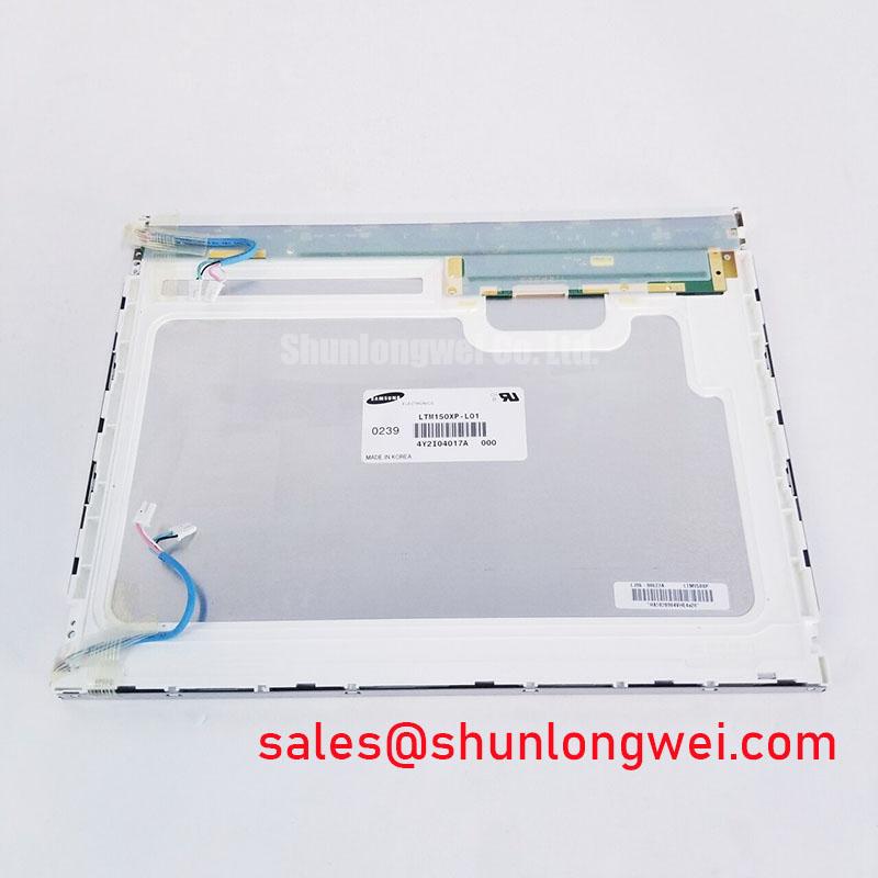
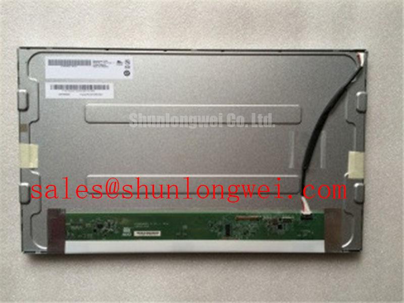
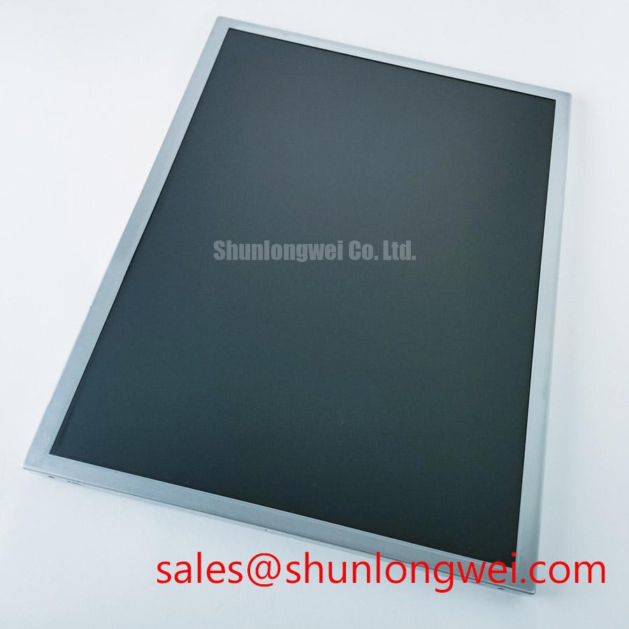
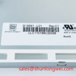
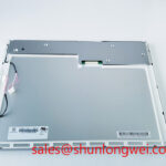
Before final acceptance, compare the replacement against the original unit for connector compatibility, image orientation, startup sequence, brightness control, visible area, mounting fit, and behavior during thermal transition. The official product identity available for this page is AUO G150X1-L01, categorized as an Industrial Grade LCD/HMI Panel and packaged as a TFT LCD Display Module. Any unlisted electrical, optical, mechanical, or environmental parameter should remain subject to documentation review and system testing.