
Content last revised on September 10, 2026
IEEE 61000-4-5 Industrial Surge Immunity: Metal Oxide Varistor (MOV) Integration
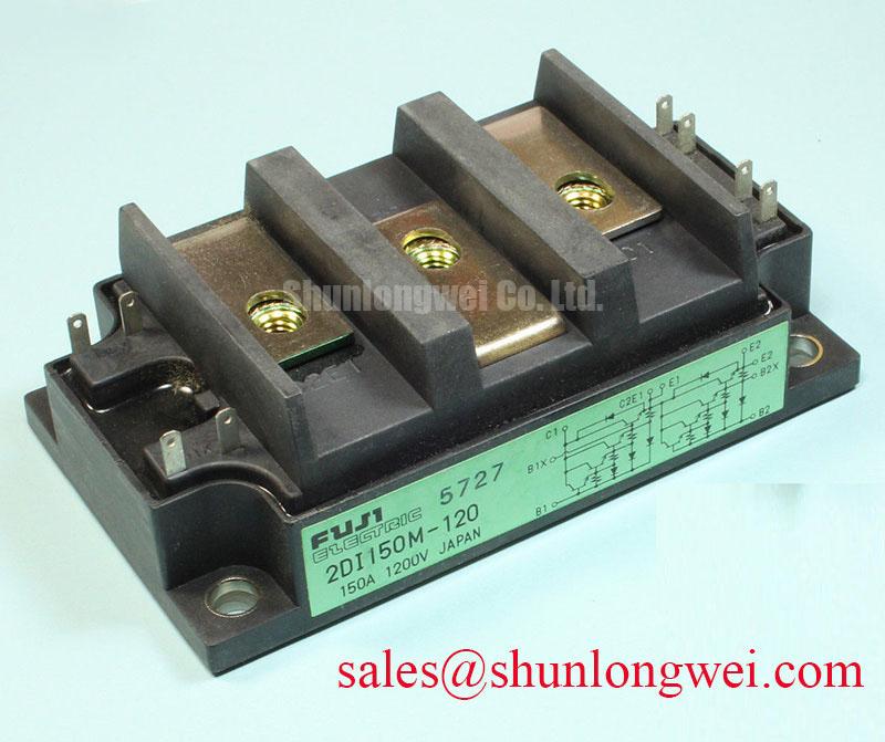
When qualifying the 2DI150M-120 dual power Darlington transistor module on the incoming inspection bench, verifying absolute maximum ratings is the first step toward robust line-side survivability. In high-voltage three-phase motor solid-state soft starters operating on 380V to 480V AC distribution lines, transient surges defined by standard IEEE 61000-4-5 can exceed several kilovolts. The Fuji Electric 2DI150M-120 features a collector-emitter breakdown rating of VCES = 1200V and a collector-emitter sustaining voltage of VCEO(sus) = 1200V.
To prevent localized junction breakdown during lightning strikes or inductive line switching, standard industrial design guidelines place heavy-duty metal oxide varistors (MOVs) in line-to-line and line-to-ground configurations directly ahead of the power stage. These clamping devices limit transient excursions below the critical 1200V threshold. An RC snubber network connected across the primary collector-emitter terminals dampens high-frequency ringing and limits dV/dt transients during phase-angle firing. Engineers cross-referencing factory parameters can review the Fuji Electric Power Semiconductors Portal for standardized voltage margin criteria across variable-speed systems.
Semiconductor Protection Fuse Selection in High-Capacity AC/DC Industrial Power Supplies
Protecting power stages against short-circuit events requires coordinating semiconductor fast-acting fuses with the thermal and current limits of the power block. The 2DI150M-120 delivers a continuous collector current rating of IC = 150A, a peak collector current of ICP = 300A (1 ms pulse), and a maximum total power dissipation of PC = 1000W at a case temperature of 25°C.
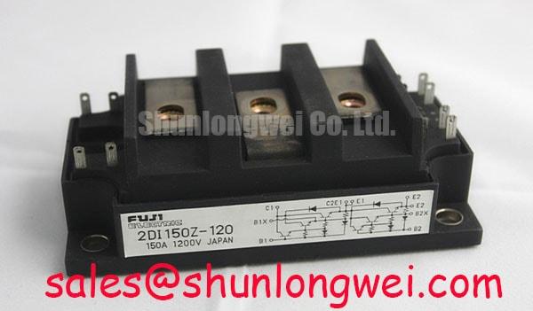
During dead-short conditions, the clearing energy (I2t) of the ultra-rapid semiconductor fuse must remain strictly below the non-repetitive surge withstand capability of the silicon die. If the fuse clearing time lags, excessive adiabatic heating can destroy the junction bonding wires. In systems where front-end rectification feeds downstream switching banks, the companion 2DI150Z-120 serves as a baseline for matching loop inductance and fuse clearing envelopes across multi-stage converter architectures.
| Parameter Description | Symbol | Factory Absolute Maximum Rating | Test / Operating Condition |
|---|---|---|---|
| Collector-Emitter Voltage | VCES / VCEO(sus) | 1200 V | Base-Emitter Shorted / Open |
| Continuous Collector Current | IC | 150 A | Continuous DC |
| Peak Collector Current | ICP | 300 A | 1 ms Pulse Width |
| Continuous Base Current | IB | 9 A | Continuous DC |
| Emitter-Base Voltage | VEBO | 7 V | Collector Open |
| Maximum Power Dissipation | PC | 1000 W | TC = 25°C, per module |
| Isolation Voltage | Visol | 2500 V AC | 1 Minute, Terminals to Base |
| Operating Junction Temperature | Tj | +150 °C | Continuous Operation |
Current-Limit Mode vs Linear Voltage Ramp Selection in Large Motor Soft Starters
In high-inertia motor starting applications, selecting between a linear voltage ramp and closed-loop current-limiting directly dictates the thermal stress on the module. Uncontrolled direct-on-line starting exposes windings to 6x to 8x rated inrush currents. Modulating the conduction angle of the 2DI150M-120 restricts inrush current to less than 2.5x rated motor current, smoothing mechanical acceleration.
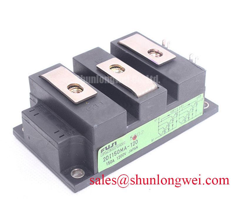
Because the module requires an active base drive current of up to IB = 9A, driver stages must supply adequate charge during ramp-up while observing the VEBO = 7V reverse limit. For field maintenance operations requiring a direct replacement with alternate mounting or internal gain characteristics, the compatible 2DI150MA-120 provides an equivalent 1200V, 150A footprint for retrofits.
💡 Bench Tip: During incoming quality inspection, always use a calibrated four-wire digital multimeter to measure the cold-state forward voltage drop (VF) of the integrated free-wheeling diodes across terminals C2E1-E2 and C1-C2E1. Ensure proper anti-static ESD grounding before handling; exceeding the 7V VEBO limit via ungrounded probe contact can degrade the base-emitter input stage.
Non-Repetitive Surge On-State Current (I_TSM) & Post-Fault Blocking Capability
Motor stall events or transient supply dips subject the silicon to intense thermal cycles. The junction temperature can approach its operating ceiling of Tj = +150°C. Following a high-current surge event, the internal Darlington structure must retain its full post-fault blocking capacity without exhibiting excessive leakage current when reverse voltage reappears across the AC cycle.
Standard field installation guidelines typically recommend mounting the module baseplate to a milled heatsink using M5 screws torqued uniformly between 2.5 and 3.5 N·m, alongside a 50 to 80 µm layer of high-conductivity thermal grease. Maintaining thermal impedance ensures that the internal base-collector junctions cool rapidly below maximum ratings before continuous line voltage is reapplied. Detailed inspection methodologies and thermal resistance verification procedures are documented in the Field Engineer’s Handbook. For broader component line specifications and module outlines, consult Fuji Electric Global Power Semiconductor Technologies.
Electrical safety during bench testing is confirmed via the integrated isolation barrier rated at Visol = 2500V AC for 1 minute between the external power terminals and the isolated copper baseplate.