Content last revised on September 28, 2026
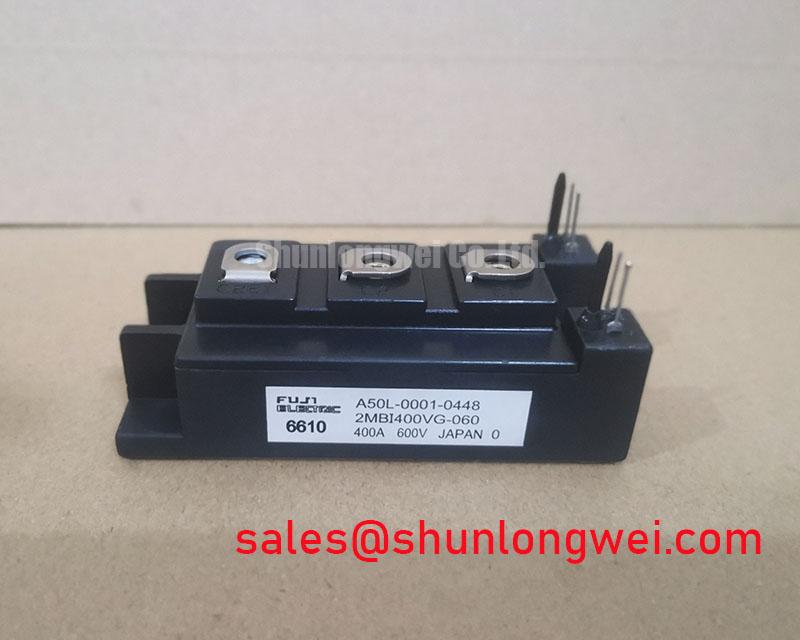
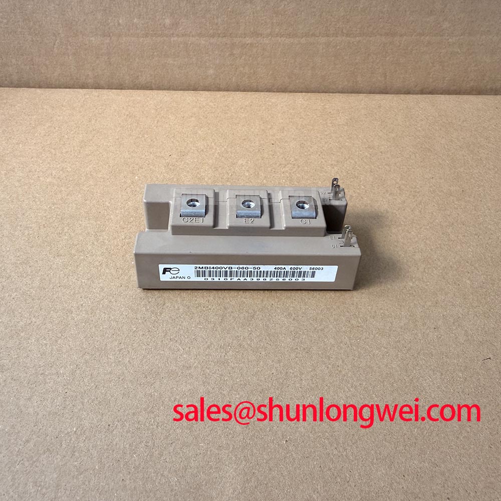
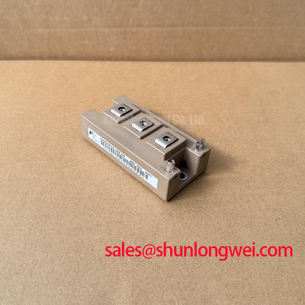
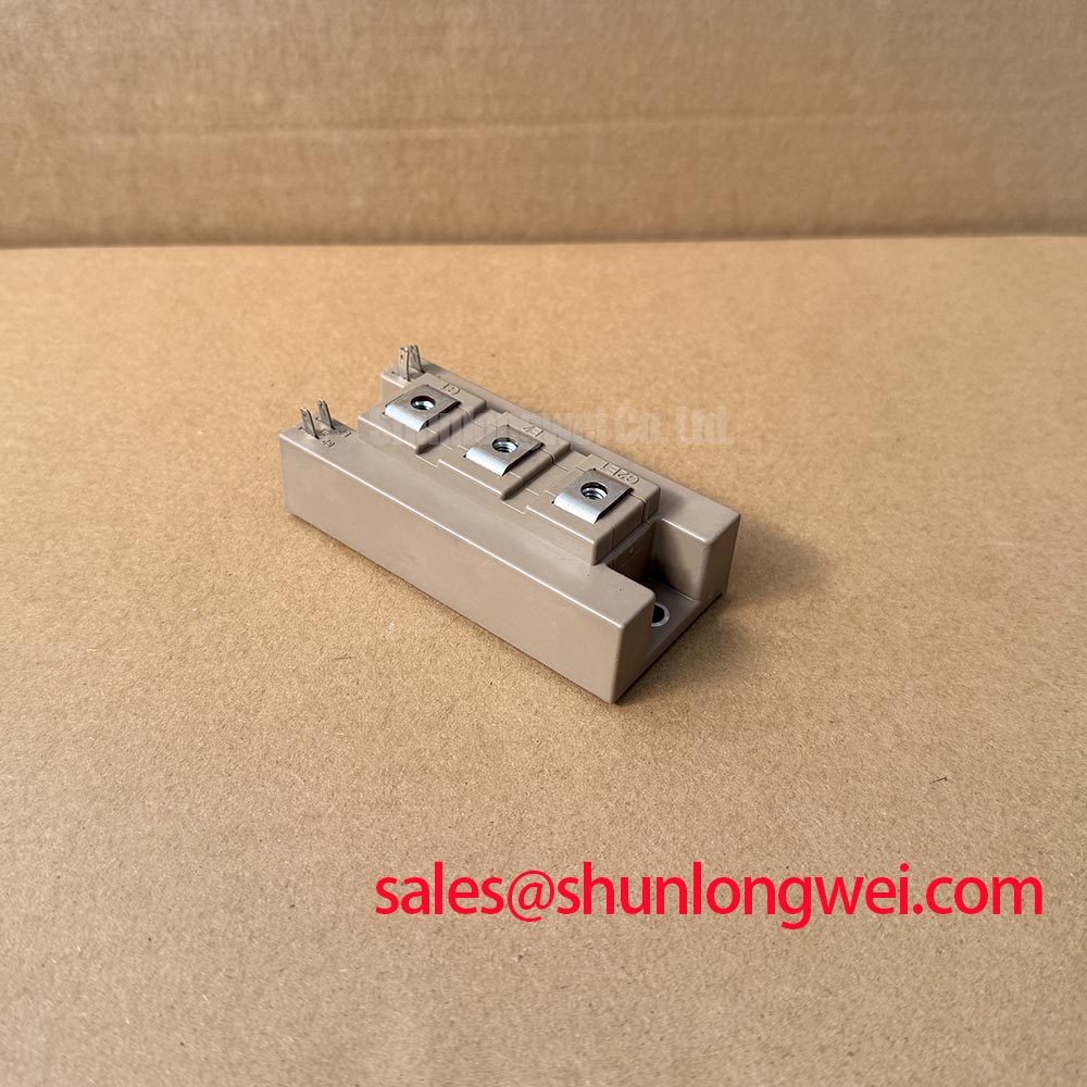
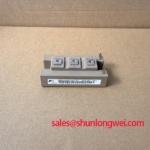
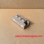
Fuji Electric 2MBI400VB-060-50 Dual IGBT Module
Product Overview & Technical Highlights
Optimizing Thermal Overhead and Switching Efficiency in Low-Voltage Inverters
The 2MBI400VB-060-50 is a high-performance 600V, 400A dual-channel IGBT Module belonging to the V-series family from Fuji Electric. For system designers targeting motor control and backup power infrastructure, this module provides an optimized balance of low conduction losses and high thermal limits, supporting continuous operation up to a maximum junction temperature (Tj) of 175°C. By upgrading key silicon characteristics, it enables compact converter packaging without sacrificing over-temperature margin.
For 400V power systems prioritizing maximum thermal safety margin and conduction efficiency, the 2MBI400VB-060-50 serves as a robust switching block. What is the primary benefit of its V-series chip structure? Minimizing conduction losses through a low on-state voltage drop. This translates directly to less heat generation under high-load cycles.
Key Parameter Overview
Decoding the Specs for Enhanced Thermal Reliability
The following parameters represent the absolute maximum ratings and electrical characteristics verified by the manufacturer's engineering documentation at Tc=25°C unless otherwise specified:
| Parameter Description | Symbol | Rated Value / Condition | Unit |
|---|---|---|---|
| Collector-Emitter Voltage | VCES | 600 | V |
| Gate-Emitter Voltage | VGES | ±20 | V |
| Continuous DC Collector Current | IC | 400 (Tc = 80°C) | A |
| Pulsed Collector Current | IC pulse | 800 (1ms pulse width) | A |
| Collector Power Dissipation | PC | 1970 (1 device operation) | W |
| Max. Junction Temperature | Tj | 175 | °C |
| Operating Junction Temp. (Switching) | Tjop | 150 | °C |
| Isolation Voltage | Viso | 2500 (AC for 1 minute) | VAC |
| Collector-Emitter Saturation Voltage | VCE(sat) | 1.90 (Typical at IC = 400A) | V |
Download the 2MBI400VB-060-50 datasheet for detailed specifications and performance curves.
Application Scenarios & Value
Achieving System-Level Benefits in High-Frequency Power Conversion
Engineers often face critical thermal limits when scaling current density in compact cabinet designs. The 2MBI400VB-060-50 directly mitigates these challenges through a low-inductance packaging layout and high-speed switching capabilities. This makes the module highly applicable in standard industrial equipment, including Variable Frequency Drives (VFD), AC/DC servo amplifiers, uninterruptible power supply (UPS) systems, and industrial welding power systems.
Consider a heavy machinery application, such as a factory conveyor line driven by a VFD. During startup, the motor draws a high surge current. The 2MBI400VB-060-50 accommodates these events via its peak pulse current capability of 800A. By reducing parasitic layout inductances internally, the module minimizes the inductive voltage spikes (V = L * di/dt) that occur during rapid turn-off phases, protecting the silicon from transient overvoltage. This electrical ruggedness is comparable to a shock absorber on a vehicle, smoothing out transient spikes to protect the broader drive circuitry.
For systems that demand alternative power ratings or structural variants in the design phase, trade professionals may also evaluate the related 2MBI300VB-060-50 for lower current requirements, or the higher-capacity 2MBI600vd-060-50 when current demands scale up.
Technical Deep Dive & Thermal Performance
Unlocking Power Density via V-Series Silicon and High-Temperature Package Limits
The thermal design of high-power converters hinges heavily on the interface between the silicon junction and the cooling heatsink. Under severe operating conditions, heat generation is determined by the combination of switching losses and conduction losses. The 2MBI400VB-060-50 addresses conduction efficiency with a typical VCE(sat) of 1.90V. This lower voltage drop acts like a wider valve in a fluid pipe, reducing resistance and keeping heat generation to a minimum while carrying high current loads.
Furthermore, the module raises the thermal ceiling with a maximum junction temperature rating of 175°C. By allowing the silicon to operate safely at higher peak temperatures during overload conditions, system designs can utilize smaller heatsinks or reduce forced-air cooling requirements. This directly supports the development of higher power density inverter stages, meeting strict IEC 61800-3 standards for industrial motor drives without requiring oversized cooling enclosures.
Frequently Asked Questions
How does the maximum junction temperature of 175°C impact overall system reliability?
The upgraded 175°C junction temperature limit provides a crucial buffer during temporary overloads, reducing the risk of thermal runaway and extending the overall power cycling lifetime under harsh industrial environments.
What precautions should be taken regarding the mounting and terminal torque?
To maintain proper thermal contact and prevent mechanical damage to the internal ceramic substrates, both mounting screws and electrical terminals must be tightened to the specified torque of 3.5 N·m. Deviation from this value can lead to localized hot spots or cracked housings.
How does the low-inductance packaging design benefit high-frequency switching circuits?
A low-inductance module structure reduces the internal stray inductance. This minimizes the turn-off voltage overshoot, allowing designers to either simplify the external Snubber Circuit or operate the module at higher switching frequencies with lower losses.