



Content last revised on September 21, 2026
6MBP100RTJ060 Operational Boundaries: Evaluating High Altitude and Cosmic Ray Induced SEB Failure Limits
For a replacement assessment, first compare the inverter DC bus, switching waveform, and protective limits with the module’s official 600.0 V voltage rating. A high altitude installation can change the surrounding electrical and thermal environment, while atmospheric radiation effects require application specific reliability analysis. The available product data supplied for this page does not establish a FIT rate, a cosmic ray induced Single Event Burnout probability, or a universal altitude derating curve for this model. Those values must not be inferred from the voltage rating alone.
At sites above the normal installation altitude, the design team should review insulation coordination, creepage, clearance, cooling effectiveness, and the actual DC link transient profile together. The useful field measurement is not a single resistance reading. Capture the voltage at the module power terminals during turn off, including overshoot, ringing, and recovery behavior, then compare the waveform with the maximum operating conditions stated in the applicable Fuji Electric documentation. The system engineer should determine the required voltage headroom from measured switching peaks, fault clearing time, control response, and the complete protection network.
Layout inspection should focus on the commutation loop, busbar spacing, capacitor position, and the physical relationship between the module and its snubber or surge absorber. Minimize parasitic inductance in the high current path to reduce turn off overshoot, but validate the result under the highest expected DC bus, temperature, load current, and switching condition. A MOV or other transient absorber can be evaluated as part of the equipment protection network; its energy rating, clamping behavior, and coordination with fuses or active protection remain system design responsibilities.
During service troubleshooting, record the cold state condition before applying power. Check for unexpected conductive paths between the power terminals and gate control terminals with a properly isolated instrument, then compare the readings against a known good reference and the original equipment documentation. A low resistance reading may reflect circuit topology, connected protection components, or device damage, so it should be investigated with the module isolated from the gate driver and bus capacitors discharged.
Fuji Electric’s Power Semiconductor and IPM Modules resource provides manufacturer context for product families, while the exact terminal definitions and operating limits should be taken from the documentation associated with the specific device and equipment revision.
Assembly Integrity and Layout Architecture: Suppressing Cres Induced Gate Voltage Spikes
Gate circuit inspection should begin with polarity and reference verification rather than an immediate powered replacement. Confirm that every control connection corresponds to the original inverter schematic, that the driver return follows the intended power reference, and that no connector has been shifted during service. The supplied product information identifies the package and main voltage and current ratings, but it does not provide a verified gate threshold, gate charge, internal capacitance, recommended gate resistance, or mandatory negative bias value for this page. These parameters must be checked in the relevant Fuji Electric data documentation.
High dv/dt at the switching nodes can couple through device capacitances and the physical gate loop. This can produce an unwanted gate voltage excursion or create cross conduction if the complementary switching devices overlap. As a Design Consideration, the gate driver should provide controlled turn on and turn off, a suitable dead time, and a defined off state. An active Miller clamp may be evaluated where the driver architecture supports it, but its current capability, timing, isolation, and reference placement must be validated against the complete module circuit.
A negative turn off bias is sometimes used in high dv/dt power stages, but it is not an automatically valid setting for this model. The designer should confirm the permitted gate emitter voltage range, driver isolation behavior, startup sequence, and fault response before applying any negative bias. Common mode ground bounce should be examined with a differential probe at the module terminals, not assumed from a driver board test point. Keep the gate loop compact, separate high current commutation paths from sensitive control traces, and use a defined return route rather than relying on a broad chassis connection.
When modules are connected in parallel, the complete electrical and thermal arrangement must be checked. Positive temperature behavior of conduction voltage can support current sharing in some operating regions, but it does not remove the need for matched parasitic paths, equal busbar geometry, synchronized drive signals, and individual protection review. Symmetrical laminated or closely coupled busbar construction is an Engineering Recommendation for reducing unequal stray inductance. Validate current sharing with thermal measurements and current probes during startup, steady load, and transient operation.
The 6MBI100L-060 can be reviewed as a separate Fuji Electric module option during a neutral cross reference exercise. It should not be treated as a direct substitute until terminal arrangement, electrical ratings, gate requirements, mechanical fit, thermal interface, and inverter control compatibility have all been verified.
💡 Bench Tip: Use ESD protection and compare isolated, cold state terminal measurements with a known good unit before connecting the replacement to a charged DC link.
Transient Dynamics and Electrical Design: Transient Thermal Impedance for 6MBP100RTJ060
Short overload events should be assessed through the full transient thermal path rather than by comparing average current with the 100.0 A rating. The relevant path includes semiconductor losses, the module baseplate, the thermal interface, the heatsink, airflow or coolant conditions, and the duration and repetition of the pulse. The official product data supplied here does not include a Zth curve or a complete thermal RC network, so a numerical peak junction temperature cannot be calculated responsibly from the headline current rating alone.
For an Engineering Calculation, the design team can use the manufacturer’s transient thermal impedance curve, switching loss data, conduction loss data, case temperature, and the actual pulse profile. A multi RC representation may then be fitted to the published curve and convolved with the time varying power loss. Peak junction temperature should be checked against the permitted operating boundary under the worst credible pulse sequence, not just the first pulse. If the required thermal curves are unavailable, use measured case temperature and electrical waveforms to identify the missing design margin rather than inventing a thermal limit.
Oscilloscope work should include the DC link, switch node, gate signal, and current waveform with probes rated for the common mode environment. Look for delayed turn off, excessive ringing, unequal current sharing, and a gate signal that does not follow the driver command. These observations can indicate layout inductance, driver timing, measurement reference error, or a degraded power stage, but none should be assigned to one cause without isolating the connected circuit.
For a commercial string inverter or micro grid energy storage converter, the cooling assessment should include cabinet airflow, filter loading, heatsink contact, ambient temperature, altitude, and overload control. Designers should verify the actual thermal response during commissioning and after the enclosure reaches steady operating temperature. A thermal camera can help locate imbalance, but its emissivity setting and viewing angle must be controlled; use attached temperature sensors or calibrated case measurements when making a design decision.
Fuji Electric’s PIM power integrated module reference can help engineers understand the manufacturer’s broader module terminology. It does not replace the specific electrical, thermal, and mechanical documentation required for the 6MBP100RTJ060 installation.
6MBP100RTJ060 Thermal Electrical Optimization: Baseplate Contact and Screw Practical Tuning
Before mounting, clean the heatsink surface, inspect the module baseplate and mounting holes, and confirm that the mating surfaces are free from burrs, particles, and old interface compound. The thermal interface material should form a continuous, controlled layer without excessive thickness or trapped air. Its specified material, application method, compression behavior, and temperature capability must come from the selected TIM documentation and the equipment assembly procedure rather than from an assumed universal value.
Baseplate flatness and local convexity can affect contact pressure. A rigid heatsink may bridge the center or load one edge if the surface is uneven, while an overly compliant interface can increase thermal resistance. Inspect the complete mounting stack, including washers, spring elements, clamping plates, and threaded inserts. If the assembly uses disc springs or controlled pressure hardware, calibrate the installation method against the equipment manufacturer’s procedure and verify that the pressure is distributed across the intended mounting area.
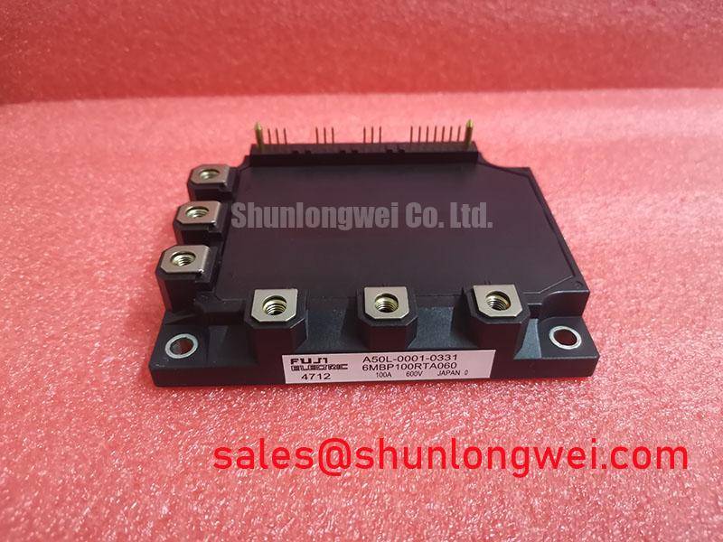
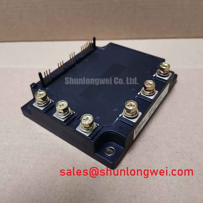
Use a sequential tightening pattern that distributes load gradually across the module rather than fully tightening one fastener before the others. The correct torque is an Official Specification only when stated in the applicable mechanical documentation; the package rating of 600.0 V and 100.0 A does not define a safe screw torque. A calibrated torque tool, clean threads, and the specified fastener condition are necessary for repeatable assembly. After mounting, inspect for baseplate distortion, interface compound displacement, and any movement of insulated standoffs or terminal hardware.
Double sided cooling or a pressure plate may be considered only when the module construction and equipment design explicitly support it. Do not assume that adding a second heatsink improves performance without checking electrical isolation, pressure distribution, thermal expansion, service access, and insulation coordination. After assembly, measure case temperature at comparable load points and compare phase or channel behavior. A persistent temperature difference should prompt inspection of contact pressure, busbar symmetry, gate timing, current sharing, and sensor placement.
For reliability documentation and failure analysis planning, engineers can consult the Field Engineer’s Handbook. The guide can support a structured inspection record, while the final acceptance criteria remain dependent on the inverter manufacturer’s service limits and the verified Fuji Electric documentation for this module.