

Content last revised on October 7, 2026
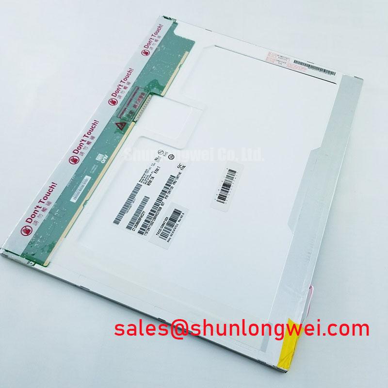
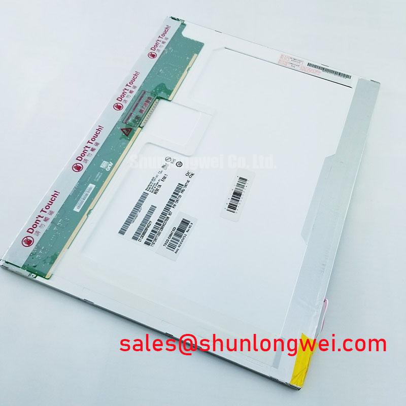
B150XG02-V4 AUO Industrial TFT LCD Display Module for HMI Applications
Begin incoming inspection by confirming the label against B150XG02-V4, checking the connector and flex area for handling damage, and recording the panel condition before applying power. The supplied factory record identifies this unit as an AUO Industrial Grade LCD/HMI Panel in a TFT-LCD Display Module package, with its specification status recorded as Official Factory Spec Verified.
This product page is intended for engineers evaluating a replacement display in industrial control equipment, medical imaging interfaces, service terminals, and other HMI assemblies. The available factory information confirms the product category and manufacturer, but it does not provide a complete public electrical table for interface voltage, pin assignment, resolution, luminance, viewing angle, contrast ratio, backlight current, optical bonding, or environmental ratings. Those values should be checked against the original panel documentation and the equipment manufacturer’s service information before installation.
| Parameter | Verified information |
|---|---|
| Model | B150XG02-V4 |
| Manufacturer | AUO |
| Product category | Industrial Grade LCD/HMI Panel |
| Construction category | TFT-LCD Display Module |
| Specification status | Official Factory Spec Verified |
| Application assessment | Suitable for engineering evaluation in compatible HMI and display assemblies, subject to system verification |
Backlight Driving, Dimming & Flicker Assessment
Do not assume that the backlight topology of this panel is WLED, CCFL, or a particular constant-current architecture unless the original panel datasheet or equipment schematic confirms it. The supplied product record does not publish a backlight type, LED rail voltage, LED current, PWM input range, dimming ratio, or optical half-life. These omissions matter when a service engineer is replacing a display in a surgical navigation or ultrasound diagnostic terminal, because an apparently compatible panel can still produce a white screen, unstable brightness, or a non-responsive dimming control if its power and interface requirements differ.
Before connection, compare the original display’s connector keying, pin numbering, supply rails, enable control, dimming signal, and ground arrangement with the replacement documentation. Power sequencing should be evaluated at the complete assembly level. The display controller should reach its specified operating state before the panel supply and backlight enable are asserted, where required by the original design. During shutdown, observe whether the controller removes the video signal, disables the backlight, and discharges the relevant rails in the intended order. A residual image or pale white screen can result from several conditions, including incorrect sequencing, missing enable control, a floating signal line, or a mismatch between the panel and controller. Use a known-good assembly and oscilloscope measurements to separate these possibilities rather than assigning a single cause from the visible symptom.
For equipment used near clinicians or operators, flicker assessment should be performed at the actual luminance settings and with the installed driver. A PWM frequency or 1000:1 dimming capability must not be attributed to B150XG02-V4 without a supporting factory specification. If the host system uses PWM dimming, verify logic-level compatibility, duty-cycle behavior, rise and fall times, and the response of the installed backlight driver. If brightness is controlled through a dedicated driver board, assess that board separately from the AUO display module.
Low-temperature response also requires system testing. Liquid-crystal response time, backlight output, cable flexibility, and controller timing can all change as the enclosure temperature moves outside the normal laboratory range. The supplied record does not establish a certified operating temperature range or a heater-strip requirement for this model. A medical equipment integrator should therefore validate startup, grayscale transitions, image retention behavior, and brightness stability inside the intended enclosure and environmental range.
Display Thermal Management & Optical Stack Verification
Thermal construction must be confirmed before modifying the display frame or adding a heat spreader. No official information supplied for this product confirms edge-lit LED rails, a PMMA light guide plate, optical bonding, an anti-glare layer, luminance level, L70/B50 life, or a direct-sunlight contrast specification. These are design attributes that may apply to some industrial panels but should not be presented as factory characteristics of this model without documentation.
When the panel is evaluated in a high-brightness enclosure, measure the temperature at the display frame, controller area, backlight region, and nearby sealing materials after the unit reaches thermal equilibrium. Keep the measurement method consistent between the original and replacement assemblies. Local heating can alter brightness uniformity, accelerate visible aging of optical materials, or change the behavior of adhesive and gasket interfaces. The correct mitigation depends on the enclosure, mounting frame, airflow, driver dissipation, and ambient conditions. System designers should verify the peak temperature against the panel and backlight limits stated in the applicable original documentation.
Direct sunlight testing should not be converted into an assumed contrast-ratio claim. The supplied factory data does not confirm a ratio above 500:1 at 50,000 lux, nor does it confirm the presence or performance of an anti-glare coating. For a sunlight-exposed service terminal, inspect the panel at several viewing angles with the intended cover glass, bezel, and illumination. Record reflected glare, black-level lifting, color shift, and loss of displayed detail. If a cover lens or optical bonding layer is used, verify that its optical stack is compatible with the replacement module and that the assembly does not introduce Newton rings, haze, or pressure marks.
Industrial HMI equipment often remains on a fixed screen for long periods. Static image retention, backlight aging, and thermal drift should be assessed using the complete display assembly rather than the panel alone. Periodic interface changes, controlled brightness, and appropriate screen-management practices may be considered by the equipment designer, but no particular burn-in performance or operating-life value is confirmed for this product record.
For a broader explanation of TFT panel selection, interface evaluation, and common reliability considerations, engineers may consult The Ultimate Guide to Industrial TFT LCD Technology while keeping model-specific decisions tied to the applicable AUO documentation.
Full-Screen Primary Color Screening: Stuck Sub-Pixels & Background Uniformity Audit
Incoming inspection should use full-screen red, green, blue, white, black, and mid-gray patterns when the compatible controller is available. View the panel directly first, then use a low-angle inspection light to distinguish a pixel defect from a surface mark or backlight irregularity. The inspection record should identify the screen position, color condition, persistence of the defect, and whether the issue follows the panel, controller, or cable when substitute parts are used.
A primary-color sequence helps expose stuck sub-pixels, inactive pixel groups, color-channel loss, and non-uniform illumination. A dark screen is useful for identifying bright points and leakage, while a white screen can reveal dark points, shading, contamination, or uneven backlight distribution. Gray patterns are valuable because they can expose subtle column behavior that is less obvious on saturated colors. These observations do not establish an acceptance limit by themselves; the applicable pixel-defect class and inspection method must come from the equipment specification or the relevant procurement standard.
A 45-degree flashlight inspection can help separate a surface or cover-layer mark from a luminous defect generated inside the display. If a line remains fixed relative to the panel image and changes with the video pattern, investigate the panel, driver region, and flex connection. If the mark changes with viewing angle or follows the surface reflection, inspect the cover, polarizer, or protective layer. COG and TAB bonding faults should not be diagnosed solely from appearance. Check the same image area at different temperatures, gently inspect the mechanical seating without stressing the flex, and compare the panel with a known-good signal source.
Color and uniformity measurements should be performed with the installed brightness setting, cover assembly, and ambient-light condition. The available product information does not specify luminance uniformity, chromaticity tolerance, contrast ratio, or factory optical calibration. For surgical or ultrasound display evaluation, the system owner should define the required grayscale visibility, color rendering, and luminance stability before acceptance. A display that produces a usable image on a bench may still require adjustment of the host controller’s timing, gamma configuration, or backlight control.
💡 Bench Tip: Wear a grounded antistatic wrist strap and support the flexible cable without forcing a sharp bend; intermittent COG or connector faults can be created during inspection if the panel is lifted by its flex.
Signal Integrity & Noise Verification in High-Vibration Bays
Signal integrity must be checked at the panel connector and at the controller output under the actual cable route. The supplied record does not confirm LVDS, eDP, RGB, MIPI, connector pinout, differential impedance, common-mode range, or eye-mask limits for B150XG02-V4. Do not rewire the panel from a similar-looking unit without verifying the original pin definition and controller compatibility.
In equipment located near variable-frequency motor drives, route the display cable away from high-current switching conductors where the mechanical design permits. Confirm shield termination, chassis bonding, connector retention, and strain relief at the enclosure level. A shielded cable is not automatically effective if its termination is interrupted by a plastic mounting bracket or a poorly bonded connector shell. Ferrite components may be evaluated as part of the host system’s EMC design, but their selection and position must be validated through signal-quality and emissions testing rather than assumed to solve every horizontal band or pixel-jitter symptom.
If the verified interface uses differential signaling, use a suitable differential probe and compare the eye opening, timing stability, common-mode behavior, and error symptoms with a known-good panel and cable. If noise appears only when a motor drive changes speed, correlate the display artifact with the drive switching event, enclosure grounding, and cable movement. If the artifact remains with the drive disconnected, inspect the controller supply, panel timing, connector contact, and display configuration. This method avoids treating one visual symptom as proof of a single failed component.
Vibration testing should include connector retention and cable strain, not only the display image. Secure the panel through its intended mounting points and verify that the frame does not transfer concentrated pressure into the glass or flex region. The appropriate vibration level, duration, EMC target, and insulation requirements are system specifications and are not established by the supplied factory record for this AUO module. Before deployment in a medical or industrial terminal, complete power-sequence, optical, mechanical, thermal, and signal-integrity verification with the final controller and enclosure.