Content last revised on June 26, 2026
LM150X05-E2: Engineering a Robust 15.0-inch XGA Display for Industrial Longevity
Product Overview
Delivering Consistent Visual Performance for Demanding HMI and Control Systems
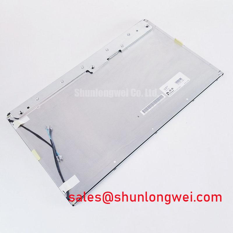
The LM150X05-E2 is a 15.0-inch a-Si TFT-LCD module engineered for long-term reliability in industrial applications. It delivers consistent XGA resolution in a classic 4:3 aspect ratio, making it an ideal component for upgrading or maintaining legacy control systems where form factor and interface compatibility are critical. With its focus on operational robustness over a wide temperature range and a design that prioritizes serviceability, this display provides a stable and predictable visual interface for complex machinery and process control environments. For legacy industrial HMIs requiring a robust 4:3 display, the LM150X05-E2 is a premier choice for drop-in compatibility and extended service life.
- Key Specifications: 15.0-inch Diagonal | 1024x768 (XGA) Resolution | 3.3V Logic Voltage | CCFL Backlight
- Core Advantages: Excellent legacy system compatibility. Designed for industrial operating conditions.
- What is the primary benefit of its 4:3 aspect ratio? It enables direct, hassle-free replacement of older displays without costly UI redesign.
Application Scenarios & Value
System-Level Benefits in Legacy System Migration and Industrial Automation
The LM150X05-E2 is engineered to solve a common challenge in the industrial sector: extending the life of high-value capital equipment. Consider an engineer tasked with retrofitting a fleet of 15-year-old CNC milling machines. The original HMIs are failing, but a complete control system overhaul is cost-prohibitive. The LM150X05-E2's specific combination of a 15.0-inch screen, 1024x768 resolution, and a standard LVDS interface provides a near drop-in replacement. This allows for a targeted component-level upgrade, preserving the existing Industrial PC (IPC) and costly control software. The result is a significant extension of the machine's operational life, minimized downtime, and a drastically lower total cost of ownership compared to a full system replacement.
This display's value extends to new designs in environments like factory automation, process control dashboards, and specialized instrumentation where a 4:3 aspect ratio remains the standard. Its proven architecture provides a stable, long-term procurement option, insulating designs from the volatility of consumer-driven display trends. While the LM150X05-E2 is a workhorse for standard brightness applications, systems requiring higher luminance for better readability in brighter ambient conditions might consider a panel like the G150XNE-L01, which offers enhanced brightness characteristics.
Key Parameter Overview
Functional Specifications for System Integration
The technical specifications of the LM150X05-E2 are tailored for straightforward integration into industrial hardware. The parameters below have been grouped by function to facilitate a rapid assessment by design engineers.
| Display Core Characteristics | |
|---|---|
| Screen Size | 15.0 inch |
| Resolution | 1024(RGB)×768, XGA |
| Aspect Ratio | 4:3 (Width:Height) |
| Pixel Arrangement | RGB Vertical Stripe |
| Active Area | 304.128(W) × 228.096(H) mm |
| Optical Performance | |
| Display Mode | Normally White, Transmissive |
| Luminance | 250 cd/m² (Typ.) |
| Contrast Ratio | 300:1 (Typ.) |
| Display Colors | 262K (6-bit) |
| Environmental & Mechanical | |
| Operating Temperature | 0 ~ 50 °C |
| Storage Temperature | -20 ~ 60 °C |
| Surface Treatment | Antiglare, Hard coating (3H) |
Technical Deep Dive
Design Considerations for Reliability in the Field
A key attribute of the LM150X05-E2 is its CCFL (Cold Cathode Fluorescent Lamp) backlight system. While modern displays have largely shifted to LED backlights, the CCFL design offers a distinct advantage in the context of long-term serviceability. The CCFL tubes and their associated inverters are mature, well-understood technologies. This often allows for field replacement of a failed backlight, a process analogous to changing a fuse rather than replacing an entire power supply board. For managers of large fleets of industrial equipment, this serviceability directly translates to reduced maintenance costs and minimized downtime. This contrasts with many integrated LED backlight systems where a failure necessitates replacing the entire, costly LCD module.
Furthermore, the specified operating temperature range of 0°C to 50°C ensures stable performance within the controlled environments of most factory floors and control rooms. The antiglare surface treatment is another practical feature, enhancing readability by diffusing reflections from overhead lighting—a common issue in industrial settings. This combination of serviceable design and practical surface optics underscores the module's suitability for real-world industrial use, a focus further explored in our guide to industrial vs. consumer displays.
Frequently Asked Questions (FAQ)
Why is the 4:3 aspect ratio significant for industrial applications?
The 4:3 aspect ratio is crucial for legacy compatibility. Many established SCADA systems and HMI software interfaces were designed specifically for this screen shape. Using a 4:3 display like the LM150X05-E2 allows for direct replacement of older panels without the need to re-engineer, re-test, and re-validate the user interface, saving significant time and development resources.
What is the typical lifespan of the CCFL backlight?
While datasheets often specify a minimum backlight life, typically in the tens of thousands of hours, the actual operational life depends heavily on usage patterns and environmental conditions. The key advantage of this model's CCFL system is its potential for field service, allowing the backlight to be replaced to extend the display's overall service life.
Is an external inverter required for the backlight?
Yes, the LM150X05-E2 contains the CCFL tubes but requires an external inverter to generate the high voltage necessary to power them. This modular approach allows engineers to select an inverter that best fits their system's power budget and mechanical constraints, offering greater design flexibility.
Streamlining Your Industrial Display Integration
To facilitate your design and evaluation process, our team can provide access to comprehensive documentation and technical support. If you are developing systems that require robust and reliable display solutions, contact us to discuss the specific needs of your application and how the LM150X05-E2 can meet your long-term performance and serviceability goals.