


Content last revised on September 10, 2026
Backlight and Dimming Troubleshooting for the LQ150X1LGB1
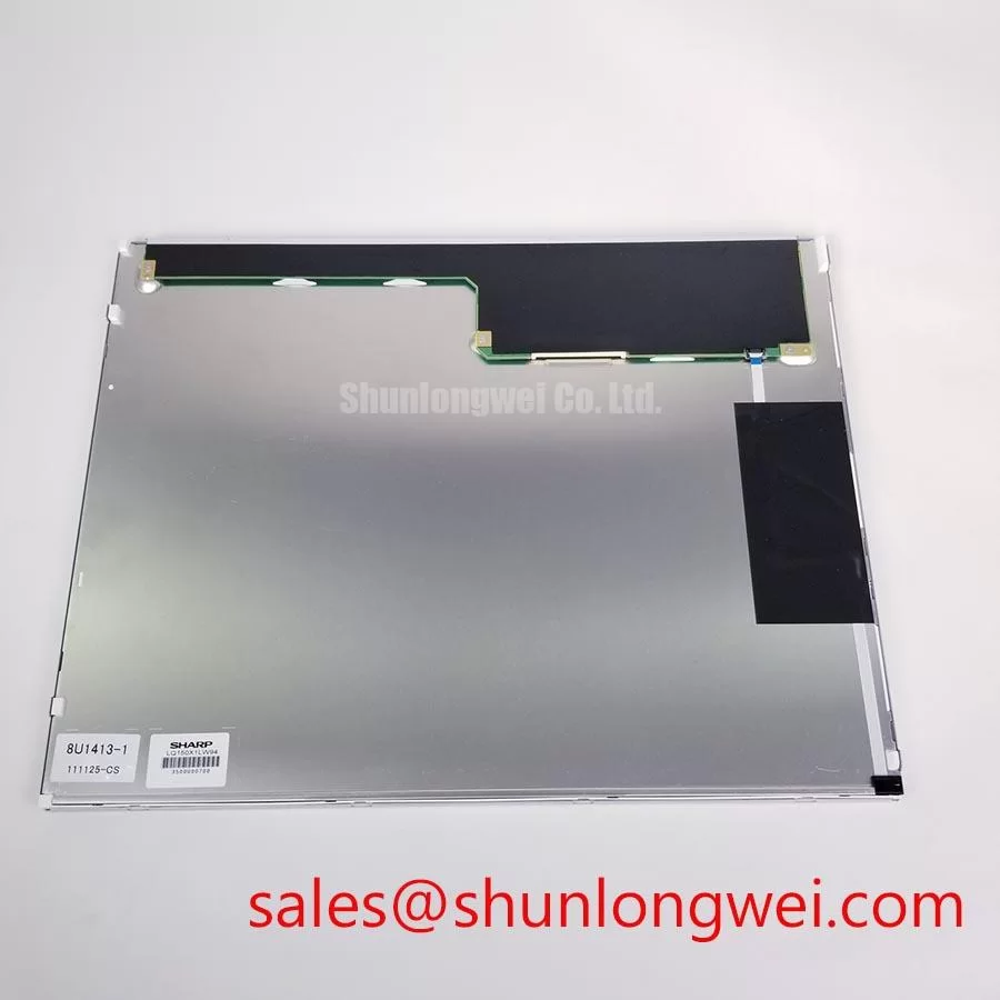
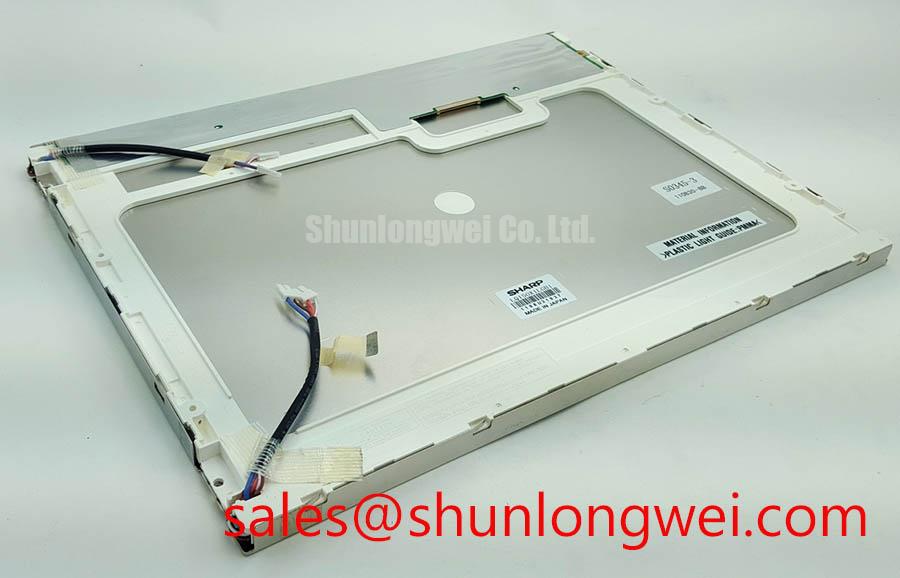
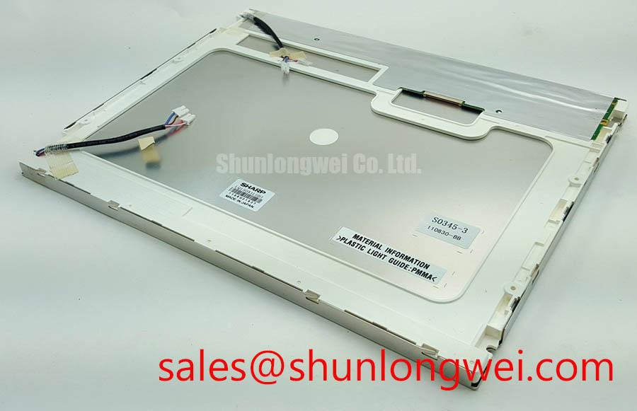
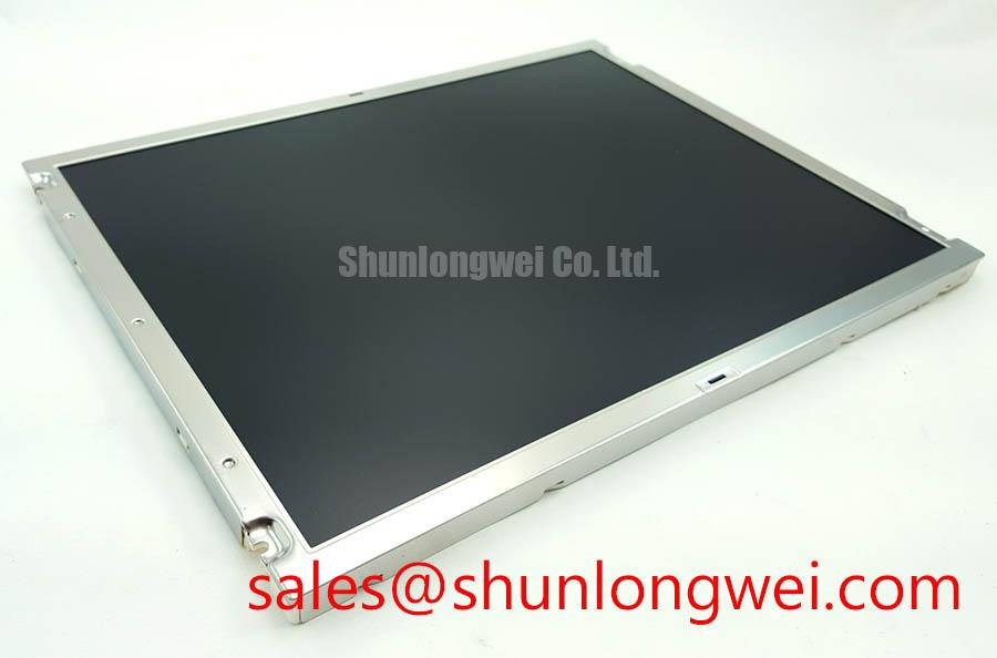
Before connecting the replacement panel, isolate the machine power, inspect the display connector and bezel for mechanical damage, and compare the nameplate with the original unit: LQ150X1LGB1 is a Sharp TFT LCD Display Module classified for industrial LCD and HMI panel use.
The available factory information identifies the manufacturer as Sharp, the product category as an Industrial Grade LCD/HMI Panel, and the package or housing as a TFT LCD Display Module. Basic product identity information is available, but electrical interface details, native resolution, viewing technology, luminance, backlight construction, operating temperature range, connector assignment, and mechanical dimensions must be confirmed from the original panel documentation or the equipment service manual before installation.
| Parameter | Available specification |
|---|---|
| Model | LQ150X1LGB1 |
| Manufacturer | Sharp |
| Product category | Industrial Grade LCD/HMI Panel |
| Package or housing | TFT LCD Display Module |
| Specification status | Basic product identity information available; detailed specifications require confirmation |
Start a black-screen inspection at the power and backlight boundary rather than assuming that the LCD glass has failed. A dark image can result from a missing panel supply, an inactive backlight circuit, a loose signal cable, incorrect enable sequencing, or a fault elsewhere in the HMI controller. The LQ150X1LGB1 product information supplied for this page does not confirm a WLED backlight, a CCFL assembly, a constant-current input, a PWM dimming ratio, a half-life rating, or a specified MTBF. Those values should not be assigned to this model without the applicable Sharp documentation.
When the original machine uses a separate backlight driver, the system integrator should verify whether that driver is electrically compatible with the replacement module. The driver output type, enable polarity, dimming method, current regulation behavior, connector pinout, and protection response all require confirmation from the original panel documentation. A display module should not be connected to a driver simply because the connector appears mechanically similar.
For a CNC operator panel or robot teach pendant, inspect the display under controlled ambient light. If the screen produces a faint image when illuminated externally, the video path may be active while the backlight path remains unverified. If no image is visible, check the controller output, panel supply, cable seating, and display enable sequence as separate conditions. Oscilloscope measurements should be taken against a known-good signal path where available, with the machine isolated from hazardous voltage.
Ambient sunlight can expose weaknesses in optical contrast, surface reflection, and viewing-angle compensation. However, the supplied factory parameter set does not specify a contrast ratio at a defined lux level, an anti-glare coating, an IPS or MVA optical mode, or a sunlight readability rating for this model. Designers evaluating the unit for a door-mounted HMI or outdoor-facing control enclosure should verify these optical requirements using the original equipment specification and an application-level display test.
Pulse-width dimming frequency and duty-cycle linearity are system-level characteristics unless explicitly listed for the panel. If visible flicker, audible driver noise, or unstable brightness appears after installation, compare the dimming waveform and enable timing with the original assembly. Do not treat a generic PWM range as an official capability of the LQ150X1LGB1.
🔧 Field Alert: Disconnect machine power and allow stored energy to discharge before inserting or removing the display cable, because contact during an active power sequence can stress signal and supply pins.
VESA vs. JEIDA Data Mapping Alignment & Even/Odd Channel Signal Integrity
Image defects that appear as a split screen, incorrect colors, vertical noise, or an unstable raster require a signal-path inspection before any optical adjustment. Confirm the controller output standard, data mapping, pixel order, clock relationship, connector orientation, and cable construction from the original Sharp documentation. The supplied specifications do not confirm whether this model uses LVDS, TTL, a particular JEIDA arrangement, a VESA mapping, single-channel transmission, or dual-channel transmission.
The system integrator should verify the required logic supply voltage from the original panel documentation. It is not appropriate to assume a nominal supply value merely from the panel family or connector appearance. Measure the actual supply at the panel connector during power-up and steady operation, then compare the result with the documented requirement for the specific display assembly.
Power sequencing deserves attention when replacing a panel in a running CNC or robot control system. The controller should establish the required supply and signal conditions in the order specified for the display, while the panel enable and backlight control should remain within the documented limits. If the screen flashes white, shows a retained image, or starts only after repeated power cycles, capture the supply and control waveforms during startup and shutdown. Such symptoms may reflect timing interaction between the controller, display, cable, and backlight driver rather than a single confirmed panel fault.
Differential routing should preserve the intended transmission environment and minimize unnecessary discontinuities. As a general Design Consideration, high-speed display pairs should be routed as a controlled differential interface with a continuous reference path, consistent pair geometry, and minimal connector transitions. The final impedance target, trace arrangement, cable length, and termination method are determined by the confirmed interface specification and the system board layout, not by the model number alone.
When the original panel uses a legacy transmitter or receiver, inspect the cable for crushed sections, oxidation, incomplete locking, and strain near the connector. A cable that passes a continuity check may still have excessive coupling or signal degradation at operating speed. Use an oscilloscope or suitable differential probe to compare clock quality and data activity with a known-good panel or controller where possible. Any jitter or timing margin assessment must be made across the actual temperature and supply conditions of the equipment.
Mapping errors can produce orderly but misleading symptoms. Even and odd pixel channels may be exchanged, color bits may be assigned incorrectly, or the controller may send a data format that the panel does not support. Verify the panel timing table and controller configuration together. Do not alter JEIDA or VESA settings by trial and error unless the machine documentation identifies the selectable formats.
For a potential comparison with another industrial display, engineers may review LMS700KF01-001 as a separate model reference. Mechanical fit, electrical compatibility, optical performance, and timing must be evaluated independently; a similar screen size does not establish interchangeability.
Industrial Bezel Mechanical Envelope Tolerances & Mounting Screw Torque Optimization
Before removing the failed display, record the bezel opening, mounting-hole pattern, cable exit direction, connector clearance, and the position of any protective cover or touch overlay. The official information available here identifies the package as a TFT LCD Display Module but does not provide confirmed outer dimensions, active-area dimensions, mounting-hole locations, screw size, bezel tolerance, or mass. These mechanical values must be checked against the original Sharp drawing or the installed equipment.
A display can fit the opening and still be unsuitable if the connector fouls the chassis, the cable is bent at the panel edge, or the bezel applies uneven pressure. Place the module on a clean, supported surface during inspection. Check for frame distortion, cracks, pressure marks, and contamination around the viewing area. Do not use the front glass or active area as a fastening surface.
Fastener loading should be treated as a Design Consideration, not an official LQ150X1LGB1 parameter. The correct screw type, thread engagement, washer arrangement, tightening sequence, and torque depend on the equipment frame and the panel drawing. Apply even loading across the mounting points and verify that the bezel remains free from local stress after tightening. If the original service manual specifies a torque, follow that documented value; otherwise, the equipment designer should establish and validate the assembly method using a fit and optical inspection.
Localized pressure can appear later as a bright spot, dark area, uneven edge, or changing mura pattern when the chassis is flexed. These observations do not by themselves prove damage to the liquid-crystal cell. Recheck the mounting frame, gasket placement, cable routing, and contact surfaces while observing the screen at a uniform test image. The result should be assessed after the enclosure reaches its normal mechanical condition, including any cover, touch interface, or sealing layer that forms part of the assembly.
Optical bonding, moisture protection, and dust sealing are application-level matters unless the factory documentation explicitly lists them for this model. Do not describe the LQ150X1LGB1 as optically bonded, sealed, or outdoor-rated without confirmation. When integrating the module into a CNC operator panel or robot teach pendant, designers should verify enclosure sealing, condensation control, cleaning-fluid compatibility, and the mechanical behavior of the complete front assembly.
Temperature can also change perceived response time and image stability. The supplied parameter set does not confirm a sub-zero operating range, gray-to-gray response time, heater requirement, or thermal-cycle qualification. If the equipment is exposed to cold storage or an unheated workshop, allow the display assembly to reach the permitted operating condition specified by the original documentation before applying demanding image tests. A heater strip, if used by the machine, must be controlled according to the equipment design rather than assumed to be part of the display module.
Preventing Frame Lag & Image Smearing in Cold Storage & Outdoor Industrial Facilities
When a replacement panel shows slow transitions or image retention in a cold environment, document the ambient condition, warm-up state, test pattern, controller timing, and backlight behavior. Liquid-crystal response is temperature dependent, but the exact operating and storage limits for LQ150X1LGB1 are not included in the supplied factory data. A definite temperature rating, gray-to-gray value, sealant performance claim, or lifetime prediction would require the relevant Sharp specification.
For equipment stored in cold warehouses, keep the display protected from condensation during transfer and startup. Moisture on connectors or behind the front assembly can create intermittent behavior that resembles a timing or panel fault. Inspect the enclosure, cable entry, gasket condition, and internal humidity-control provisions before energizing the machine. The appropriate condensation-control method is determined by the complete enclosure and operating environment.
Frame lag and smearing should be separated from transmission errors. Use a repeatable moving test pattern and compare the panel with the controller output under the same conditions. If the displayed image changes when the cable is moved, investigate connector retention, cable strain, and grounding. If the image remains stable but transitions slow as temperature changes, compare the observation with the documented response specification and the equipment’s allowed thermal window.
Clock quality, data hold time, and receiver margin should be evaluated at the interface actually used by the machine. The model information supplied for this page does not confirm a TTL or LVDS transmitter, a clock frequency, a hold-time limit, or a temperature-specific jitter margin. These values belong in the system validation record after the interface has been identified. Designers should verify peak and minimum signal conditions during startup, normal operation, dimming changes, and shutdown rather than relying only on a static continuity check.
Outdoor or exposed industrial installations also require a complete optical and mechanical review. Sunlight reflection, condensation, dust ingress, vibration, cleaning agents, and bezel pressure can influence the apparent quality of the image. The panel itself should not be represented as independently certified for EMC, environmental sealing, or a particular industrial safety standard unless that certification is explicitly documented for the assembly.
For broader background on interface selection, optical behavior, and industrial TFT integration, engineers can consult The Ultimate Guide to Industrial TFT LCD Technology. Use that information as a technical reference while confirming the actual connector, timing, optical, and environmental requirements of the machine that will receive the panel.
For procurement and repair planning, identify the original controller, cable, backlight arrangement, bezel dimensions, and documented panel timing before ordering. The LQ150X1LGB1 remains an application-specific TFT LCD Display Module, and final compatibility must be established by matching those system conditions with the original Sharp documentation.