

Content last revised on October 28, 2026
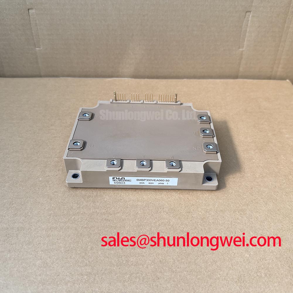
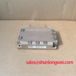
6MBP300VEA060-50 Identification and Incoming Inspection
- Isolate the DC supply, verify discharge, and compare the 6MBP300VEA060-50 terminal markings with the equipment schematic before connecting test leads.
- Record cold diode-mode readings in both polarities across the documented power-terminal paths, keeping connected circuitry out of the measurement.
- Inspect the mounting surface, terminal hardware, and insulating surfaces for contamination, uneven seating, or mechanical damage.
- Separate power-terminal checks from control-terminal tests; establish the permitted insulation-test connections before using a megohmmeter.
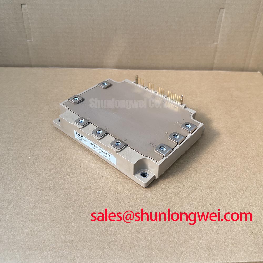
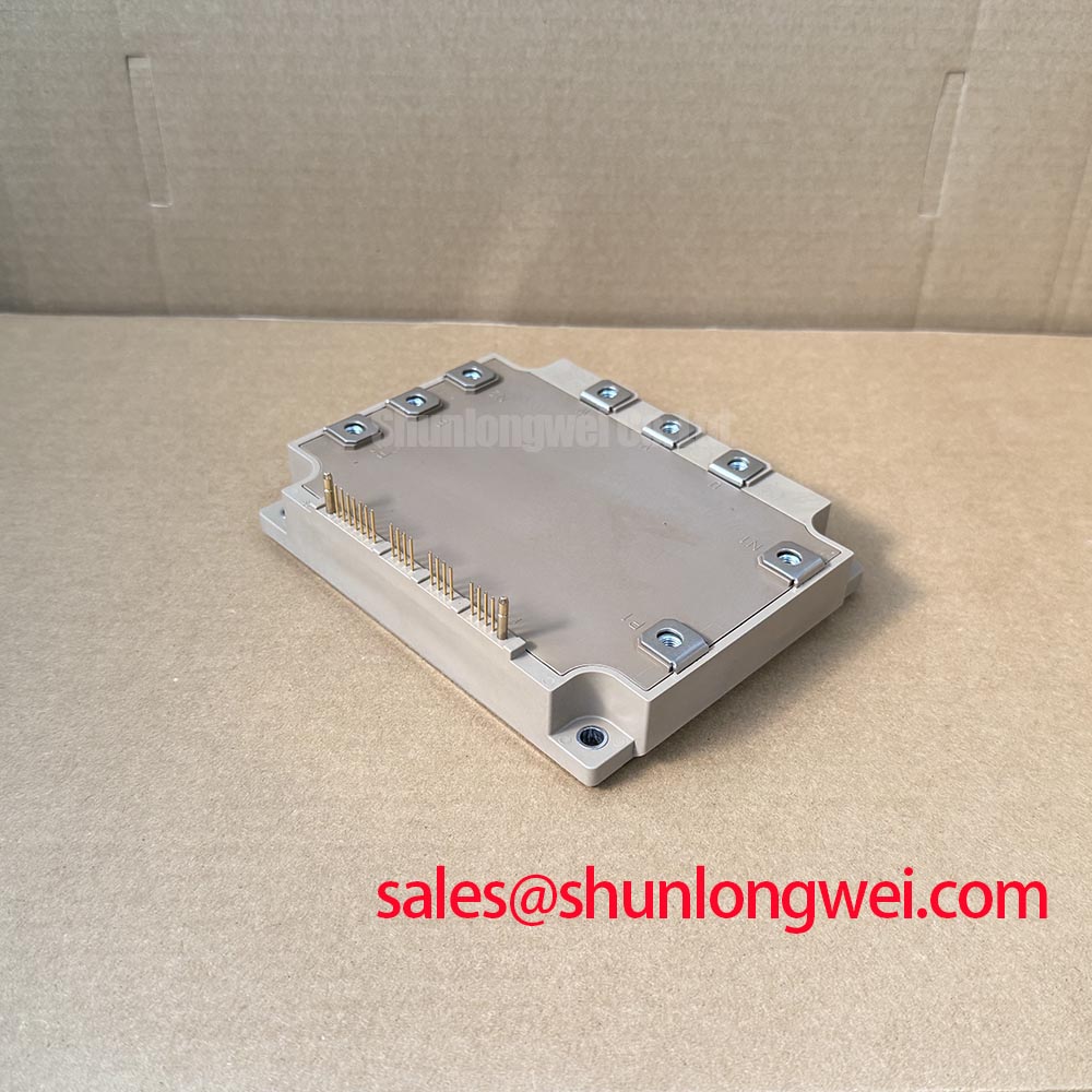
The Fuji Electric 6MBP300VEA060-50 is an IPM module with specified electrical ratings of 600 V and 300 A, subject to the datasheet rating conditions. Incoming inspection should establish terminal identity and repeatable cold-state measurements before the module enters a powered assembly. A diode-mode reading is a screening observation, not a measurement of rated-current conduction performance.
| Product identification | Specification |
|---|---|
| Manufacturer | Fuji Electric |
| Model | 6MBP300VEA060-50 |
| Product category | IPM Module |
| Voltage rating | 600 V — subject to datasheet rating conditions |
| Current rating | 300 A — subject to datasheet rating conditions |
| Package description | Fuji power module; consult the exact-model outline drawing for dimensions and mounting details. |
| Assembly and test references | Consult the exact-model datasheet for terminal assignments, rating conditions, mounting dimensions, tightening requirements, insulation tests, and protection characteristics. |
💡 Bench Tip: Use ESD-controlled handling and compare cold readings with a known-good module under identical meter polarity, temperature, and terminal connections before interpreting an apparent mismatch.
6MBP300VEA060-50 Terminal-to-Baseplate Insulation Testing
Define the terminal-to-baseplate test connections before applying insulation-test voltage. Design Consideration: insulation resistance testing, dielectric withstand testing, and switching-waveform measurement answer different questions. A megohmmeter checks leakage under its applied DC test conditions; it does not establish switching behavior, nor does a satisfactory resistance reading certify the complete equipment insulation system.
For the 6MBP300VEA060-50, the acceptance procedure should identify which power terminals are connected together, which terminals remain disconnected, and how the baseplate is contacted. Control terminals must not be included by assumption. The test voltage, duration, acceptance limit, and discharge method belong to the approved component or assembly procedure. The 600 V power-device rating is not an insulation-test instruction.
Engineering Recommendation: clean accessible insulating surfaces with a material-compatible process, allow them to dry, and document the condition before testing. Dust mixed with moisture can create a surface leakage path that complicates interpretation of a terminal-to-baseplate reading. Inspect around terminal barriers and mounting interfaces without scraping or modifying the package. A low reading warrants separating external contamination, fixture leakage, and module-related leakage through controlled repeat measurements rather than assigning an immediate internal failure diagnosis.
Keep fixture geometry consistent between samples. Contaminated clips, damp supports, and fingerprints on insulating fixtures can influence the result. Record the instrument identity, connection arrangement, environmental conditions, and reading behavior over the specified test interval. An unexpected trend should be investigated before increasing test stress. Repeated high-potential testing should follow an approved procedure rather than becoming an informal incoming-inspection routine.
For cold semiconductor screening, use the documented circuit diagram to identify the expected diode paths. Reverse the meter leads and record both observations, allowing for charging effects and any remaining parallel paths. Different readings between assemblies can originate outside the module, so disconnect associated circuitry where the service procedure permits. Neither a forward-voltage observation nor an open-circuit indication alone demonstrates operation at the rated load.
Fuji Electric’s Power Semiconductor & IPM Modules resources provide manufacturer context for the product family. Insulation acceptance should remain tied to the exact component and equipment requirements; a family description does not establish a model-specific withstand value, internal substrate material, or permissible creepage distance.
6MBP300VEA060-50 Thermal-Electrical Optimization: Terminal Screw Engagement Depth Practical Tuning
Check screw engagement against the terminal drawing with the actual lug and washer stack installed. Design Consideration: a screw can reach an apparent tightening endpoint by bottoming in a threaded feature before it clamps the connection properly. Conversely, insufficient engagement can compromise the joint. Inspect hardware length and seating rather than using tightening feel as the acceptance criterion.
Support busbars and cables so their alignment does not depend on pulling the module terminals into position. Assemble the connection without forced bending, then apply the documented tightening procedure using a suitable calibrated tool. Washer selection and stack height should follow the approved assembly drawing. The objective is a stable external electrical joint without transferring avoidable bending loads into the package; no particular internal conductor construction needs to be assumed.
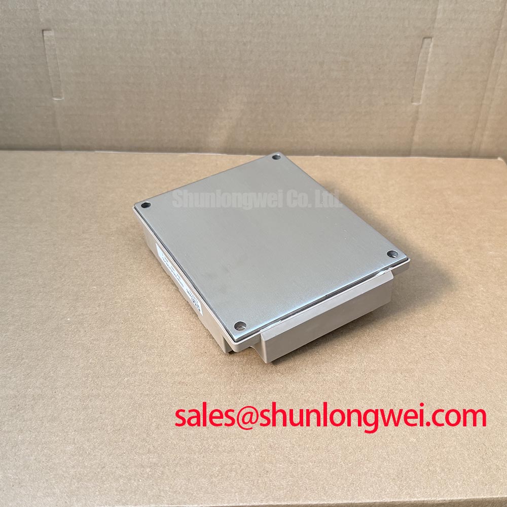
Thermal verification starts at the module-to-heatsink interface. Check mating-surface condition, flat seating, and the specified thermal-interface application process. A temperature rise at a power connection can have different origins from a rise associated with the cooling interface. Comparing terminal temperature, case measurement location, current, and cooling conditions helps separate these possibilities without treating a single hot spot as proof of semiconductor damage.
Design Consideration: transient thermal impedance, commonly identified as Zth, is relevant when the load contains short current pulses or repeated acceleration events. Evaluate the actual loss waveform against the applicable manufacturer thermal curves and their boundary conditions. A steady-state thermal resistance alone does not describe every pulse sequence. Case temperature and cooling performance should be included when assessing peak junction-temperature margin, rather than inferring it directly from the 300 A rating.
Protection coordination also requires distinguishing semiconductor behavior from the external control implementation. Desaturation monitoring observes abnormal on-state collector-emitter behavior where that protection method is used; normal saturation voltage is not itself a universal trip threshold. Blanking, detection, propagation, and current decay all contribute to the protection response. Do not assign this model an assumed detection time or two-stage soft-turn-off function. Evaluate the documented IPM protection behavior together with the host controller’s fault handling.
Where the system uses a semiconductor fuse, assess its clearing behavior against the prospective fault current, DC-link conditions, and the component protection requirements. Design Consideration: fuse I²t coordination concerns accumulated current stress during the fault, but matching an energy-related figure alone does not establish that an IGBT will survive a short circuit. Fast electronic shutdown and upstream fault isolation serve different roles; neither should be described as an unconditional rupture-prevention guarantee.
Replacement evaluation should retain this same mechanical and electrical discipline. The related 6MBP150TEA060 can be included in a comparison worksheet, but it is not established here as a direct replacement for the 6MBP300VEA060-50. Compare terminal assignments, current capability, control interface, protection behavior, thermal performance, and mounting geometry before approving any substitution. Similar model naming is not sufficient evidence of interchangeability.
Benchtop Waveform Tuning: Mitigating Stress via Long Motor Lead Reflected Wave Voltage on 6MBP300VEA060-50
Measure switching voltage at the inverter output and motor terminals as separate observations when investigating cable-related stress. Design Consideration: a motor cable behaves as a transmission path during fast voltage transitions, and impedance mismatch can produce reflected-wave overshoot. Motor-terminal overshoot and module-terminal switching overshoot are related system concerns, but they are not interchangeable measurements.
Use appropriately rated differential measurement equipment with connections suited to the switching environment. Record the DC-link operating condition, motor cable arrangement, load state, and probe location alongside each capture. Probe artifacts and common-mode limitations can resemble real ringing, so check measurement repeatability before altering the power stage. Compare the observed peak and transition behavior with the applicable component and motor insulation limits.
Output chokes and dv/dt filters should be evaluated against cable characteristics, motor requirements, switching conditions, and thermal loading. Their selection is a system decision rather than an accessory specification of this IPM. A useful validation compares the relevant waveforms and temperatures before and after the change while preserving the same operating conditions. Clearance and routing around the filter must also follow the equipment’s insulation and installation requirements.
Control-side noise deserves a separate trace through the schematic. Keep switching-current paths from sharing sensitive signal-return impedance wherever the equipment design permits, and inspect the intended shielding and grounding connections. Negative gate bias should not be introduced as a generic repair adjustment to an IPM. Work through its documented control interface and permitted supply conditions, then correlate command signals, local supplies, and fault outputs with the disturbance.
Regenerative operation can raise DC-link voltage independently of motor-cable reflection. Check the braking-control sequence, energy-transfer path, and resistor thermal condition when the reported fault follows deceleration. A braking chopper and resistor, where present in the equipment, must accommodate the actual operating duty. Increasing resistor capacity or changing control settings without evaluating the circuit can move stress elsewhere rather than resolve the original condition.
When mapping the rectifier, DC link, inverter, and associated circuits, keep each semiconductor’s actual role explicit. The 6MBP20JB060-03 is another module that may appear in a broader component comparison, not evidence of a compatible front-end rectifier or required companion stage. Fuji Electric’s Power Semiconductors Portal provides manufacturer product-navigation context for checking device families.
For electric material-handling equipment or forklift low-voltage traction, evaluate the 6MBP300VEA060-50 only against the actual inverter interface, battery operating range, regenerative conditions, cooling arrangement, and installation envelope. The broader IGBT Design & Integration guide provides supporting design context. Close the equipment test record with measured voltage peaks, fault-response observations, connection temperatures, and the approved assembly configuration so subsequent maintenance has a reproducible baseline.