
Content last revised on October 30, 2026
Benchtop Waveform Tuning: Mitigating Stress During Sinusoidal Half-Cycle Surge Current
| Manufacturer | Fuji Electric |
|---|---|
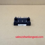
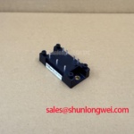
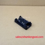
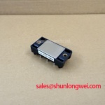
| Model | 6RI100P-160-01 |
| Category | Diode Module |
| Topology | Three-Phase Diode Bridge Rectifier |
| Rated Voltage | 1600 V |
| Rated Current | 100 A |
| Package | Power Diode Bridge Module |
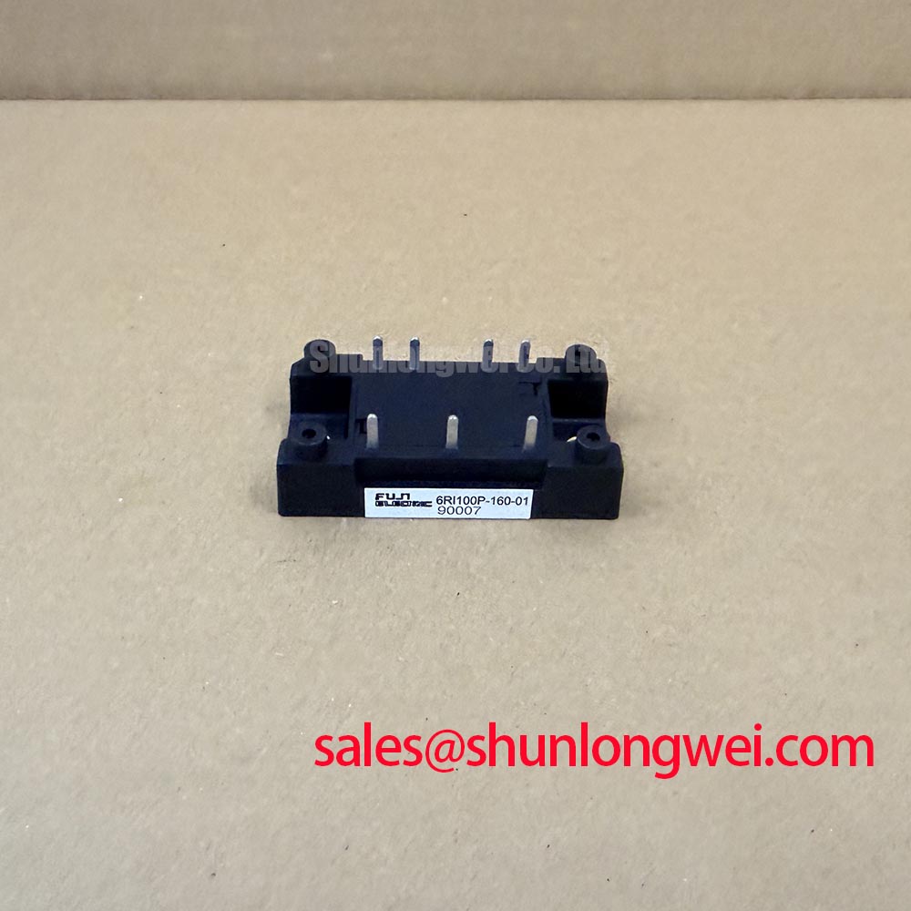
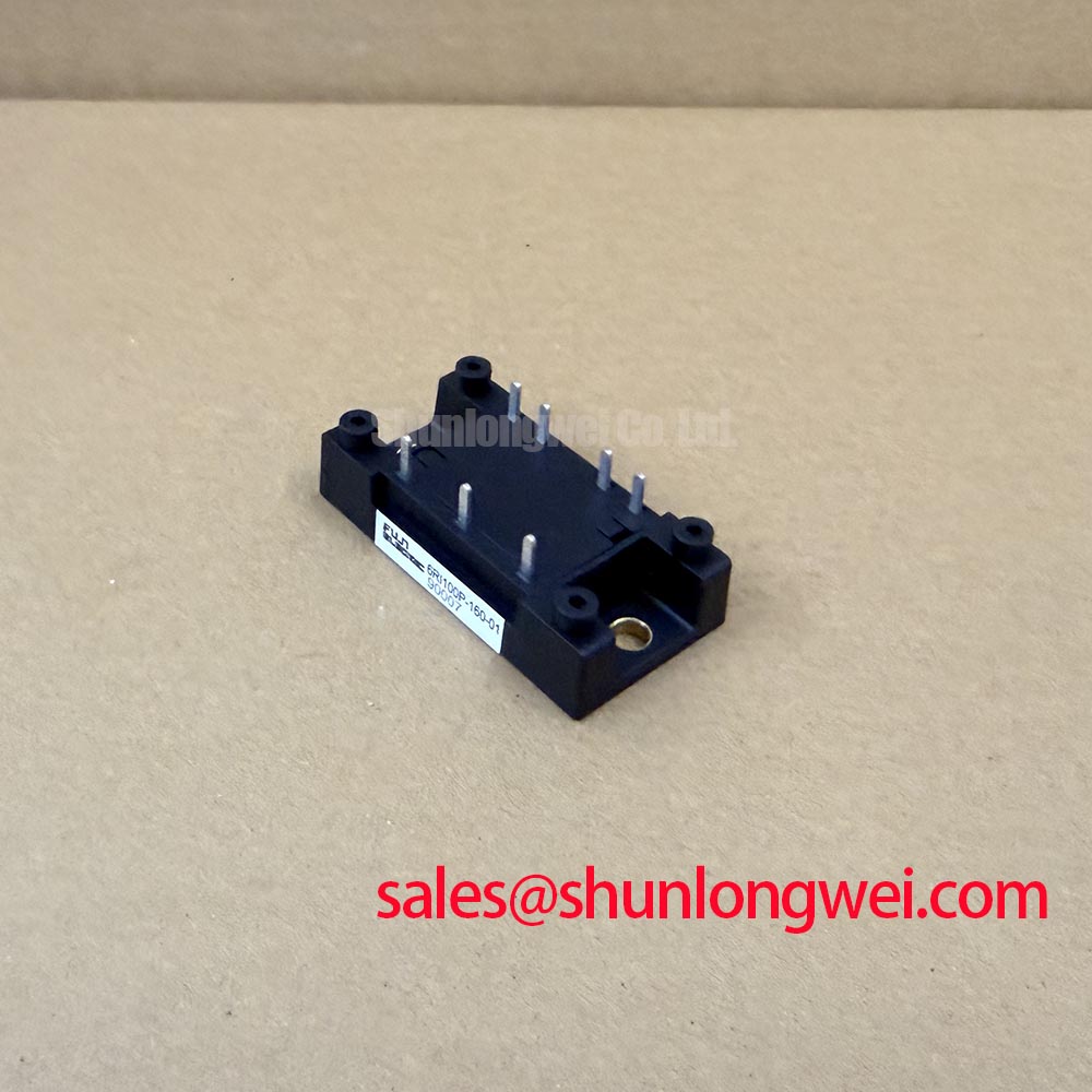
Measure each diode path with the equipment isolated and discharged, then compare the forward and reverse impedance behavior across the three-phase bridge before reconnecting the medium-frequency furnace supply. The 6RI100P-160-01 is specified as a 1600 V, 100 A Fuji Electric power diode bridge module for three-phase rectification. These are the confirmed product ratings; surge-current, ITSM, I2t, junction-temperature, and thermal-resistance values must come from the applicable Fuji Electric datasheet for the exact revision.
During a bench test, inspect the bridge output waveform with a properly rated differential probe. A distorted half-cycle, abnormal commutation notch, or unequal phase current can justify checking the upstream transformer, line reactor, fuse coordination, and connections before condemning the module. Do not infer a safe repetitive surge limit from the 100 A current rating. The continuous rating and the short-duration fault withstand capability are separate specification categories.
For a medium-frequency induction melting or hardening furnace, the semiconductor fuse must be coordinated using the manufacturer’s published clearing characteristic and I2t data. The fuse should interrupt a fault before the diode junction and package interconnects exceed their permitted energy exposure. System designers should verify the result with the actual transformer impedance, DC-link capacitance, fault loop inductance, and measured prospective current.
Assembly Integrity and Rectifier Layout Architecture
With power removed, verify terminal identification, busbar seating, and the cold impedance of every rectifier path before applying a low-energy test signal. This component is a diode bridge module, so gate-trigger measurements and gate-drive pulse-train settings do not apply to the 6RI100P-160-01. Any control pulse belongs to another device in the converter and should not be used as evidence of diode-module performance.
Keep the three-phase input conductors and DC output conductors arranged according to the converter layout so that current sharing and commutation paths remain predictable. Minimize stray inductance in the high-current loop to limit voltage overshoot during current transfer, then verify peak voltage with an oscilloscope during controlled energization. The system engineer must determine acceptable margins against the module’s confirmed 1600 V rating after measuring the real switching and wiring conditions.
Mechanical assembly is part of the electrical test. The heatsink surface should be clean and flat, the thermal interface should be applied evenly, and the terminal hardware should follow the original equipment manufacturer’s fastening specification. Field Alert: never tighten power terminals by feel or reconnect the busbar while residual DC-link voltage is present.
For a neutral comparison within the same broad power-semiconductor supply chain, engineers may review 2DI100D-100, but package geometry, terminal arrangement, topology, and electrical ratings must be checked independently before any substitution assessment.
Waveform Tuning for Voltage Sharing and RC Damping
Capture the voltage directly across the diode bridge during commutation and look for ringing, overshoot, or repeated transient peaks before selecting an RC network. The confirmed data for 6RI100P-160-01 identifies a three-phase diode bridge with a 1600 V voltage rating and 100 A current rating, but it does not establish a universal resistor, capacitor, or saturable-reactor value.
RC damping is a system-level decision. Designers should first identify the source of the ringing, including transformer leakage inductance, busbar geometry, capacitor placement, and probe connection. The selected resistor and capacitor must then be evaluated for pulse energy, voltage stress, heating, and interaction with the furnace converter’s operating frequency. Validate the finished network with measured waveforms rather than selecting values from the module current rating alone.
A series reactor may reduce current-rate stress in some rectifier arrangements, but it also changes commutation overlap, power factor, and available DC output voltage. Its suitability depends on the complete power stage and the required furnace process profile. The fuse, reactor, transformer, and bridge should therefore be evaluated as one protection and commutation network.
Where an auxiliary or preceding rectifier stage is being reviewed, 2DI150MA-050 provides a separate reference point for topology coordination. It should not be treated as an automatic companion or replacement for this Fuji Electric diode bridge.
Preventing Spurious Faults During Reverse Recovery and Commutation
Use a correctly rated differential probe to observe reverse-voltage recovery at the bridge terminals, then compare the measured current transfer and ringing with a known-good converter waveform. Reverse-recovery peak current, recovery time, softness factor, switching loss, and EMI behavior are not included in the supplied factory parameter set for this product page, so no numerical value should be assigned to them here.
Uneven recovery behavior can be influenced by line impedance, transformer leakage, stray inductance, temperature, load current, and the external damping network. Check these conditions together when a furnace rectifier produces abnormal acoustic noise, fuse operation, DC-link ripple, or radio-frequency interference. A single waveform symptom does not establish a single failed component; isolate the bridge from the surrounding network and compare each phase path under controlled test conditions.
Fuji Electric’s Global Power Semiconductor Technologies resources provide the appropriate manufacturer context for power-semiconductor application evaluation. For background on gate-drive reliability in systems containing controlled switches, engineers can also consult Evolution of Negative Off-Bias Gate Drive Circuits. That guide concerns gate-controlled devices and does not change the diode-only topology of the 6RI100P-160-01.