
Content last revised on October 28, 2026
6RI125P-160-51 Circuit Protection and Reliability: IEC 61000-4-5 Surge Coordination
Isolate the incoming supply, verify that the DC link is discharged, and disconnect parallel current paths before checking the 6RI125P-160-51 with a multimeter. Compare forward and reverse readings across corresponding rectifier paths using the equipment schematic; an unusual reading warrants further investigation, not an immediate failure verdict. Connected capacitors, suppression networks, and other semiconductor paths can influence an in-circuit measurement.
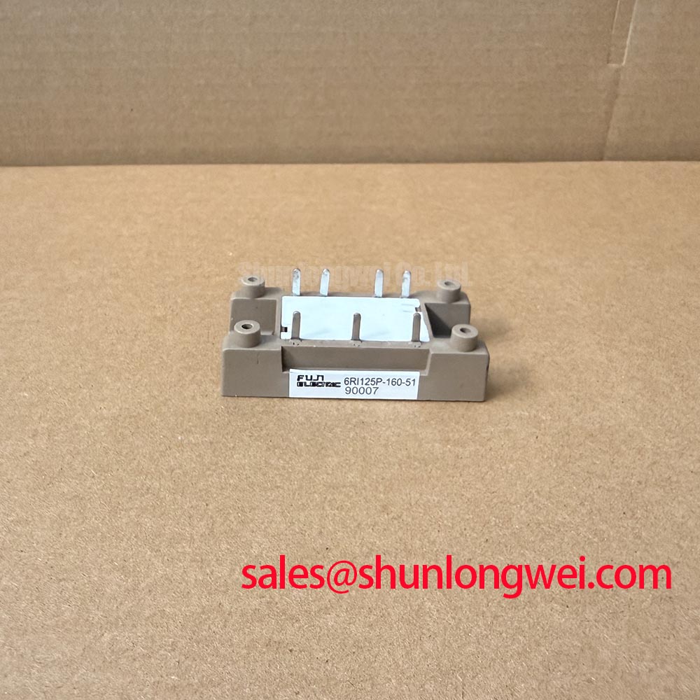
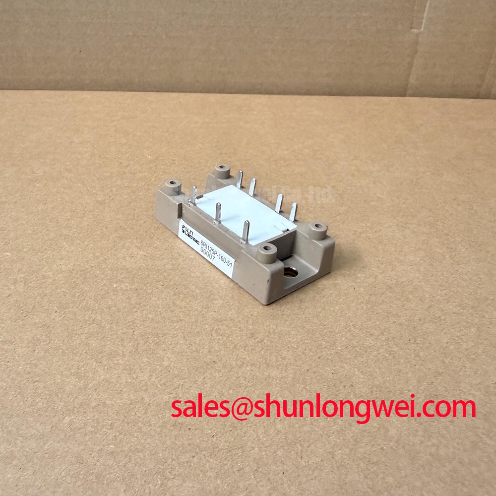
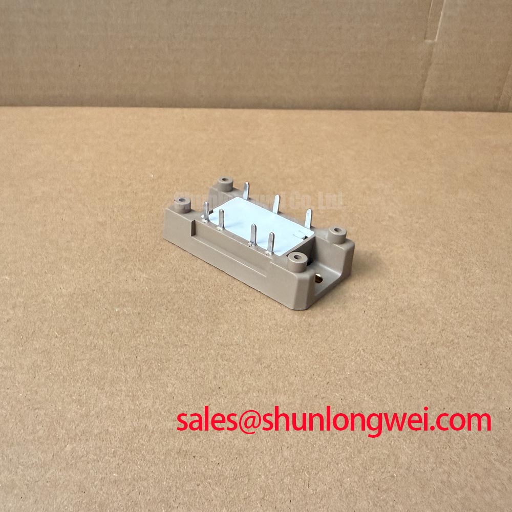
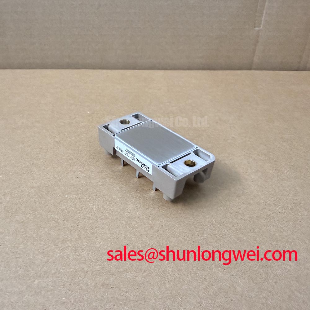
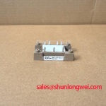
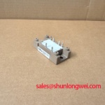
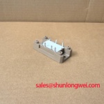
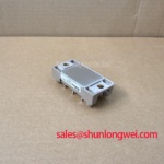
The Fuji Electric 6RI125P-160-51 is a Power Diode Bridge Module with an Official Specification voltage rating of 1600 V and an Official Specification current rating of 125 A. These are the starting points for replacement assessment. Terminal arrangement, mounting dimensions, cooling conditions, and surge capability must also match the equipment requirements.
Trace the AC input protection path from the incoming terminals through the fuses and surge suppression components before reconnecting the bridge. The relevant surge-immunity reference is IEC 61000-4-5, not IEEE 61000-4-5; it addresses equipment testing rather than certifying this diode module independently.
Design Consideration: coordinate metal oxide varistors with the supply characteristics, expected surge exposure, and upstream protection. Their residual voltage must be assessed at the protected circuit, including connection inductance. An RC suppression network should address measured ringing and component stress rather than be selected from the module’s voltage rating alone. This is a diode bridge, so thyristor gate protection and IGBT desaturation settings are not applicable module controls.
For fuse coordination, compare the fuse manufacturer’s total clearing I²t at the applicable prospective fault current with the semiconductor’s specified withstand conditions. Record the associated waveform, initial temperature, and voltage conditions alongside that comparison. A fuse carrying the same nominal current as the bridge does not establish semiconductor protection.
Use Fuji Electric Global Power Semiconductor Technologies as the manufacturer reference point for product documentation. For broader converter context, Industrial Applications provides background; equipment surge levels and acceptance criteria remain part of the system test specification.
6RI125P-160-51 Thermal-Electrical Optimization: Non-Repetitive Surge Current Assessment
Check the charging circuit and precharge operation before treating a repeated bridge failure as a steady-state overload. Capacitor charging can impose a short current pulse whose thermal effect differs substantially from normal rectifier conduction.
Design Consideration: a non-repetitive surge rating is tied to its specified pulse shape, duration, starting junction temperature, and subsequent voltage conditions. A sinusoidal half-cycle rating cannot automatically represent a capacitor-discharge event. For this diode module, use the diode surge-current designation and conditions in its datasheet rather than importing a thyristor ITSM value. Reverse voltage reapplied after the pulse must also be assessed under the manufacturer’s stated conditions.
Replacement screening should separate confirmed ratings from information still needed for installation. The linked 2DI150MA-050 is a comparison reference, not an established drop-in replacement.
| Selection checkpoint | 6RI125P-160-51 | 2DI150MA-050 |
|---|---|---|
| Manufacturer | Fuji Electric | Consult datasheet |
| Voltage rating | 1600 V — Official Specification | Consult datasheet |
| Current rating | 125 A — Official Specification | Consult datasheet |
| Package category | Power Diode Bridge Module | Consult datasheet |
| Replacement-critical details | Compare circuit diagram, terminal positions, dimensions, surge conditions, thermal ratings, and mounting torque. | |
Engineering Recommendation: inspect the heatsink contact surface and terminal hardware for uneven seating, contamination, or mechanical strain. Apply the specified interface material and fastening procedure without transferring busbar loads into the housing. Field Alert: use the specified terminal and mounting torques separately; a terminal tightening value must not be assumed suitable for the baseplate fasteners.
6RI125P-160-51 Transient Dynamics and Electrical Design: Assessing DC Ripple and Current Sharing
Map the installed rectifier connections before evaluating DC ripple, because bridge configuration and transformer connections determine the relevant current paths. Design Consideration: six-pulse rectification and twelve-pulse arrangements are system topologies, not interchangeable performance claims for an individual module.
Where a system uses phase-shifted rectifier groups and an interphase transformer, assess transformer polarity, winding characteristics, branch impedance, and measured current sharing together. Increasing the number of bridges does not establish a kiloampere output capability. Each branch needs its own electrical and thermal assessment under the actual cooling conditions.
In a high-current green hydrogen electrolyzer DC power rectifier compatibility assessment, designers should verify the bridge’s connection scheme, current waveform, and cooling arrangement against the equipment drawings. A separate module such as RM10TA-2H should be evaluated by its documented circuit role, not presumed compatible with the main bridge or auxiliary rectification stage.
Engineering Recommendation: measure loaded DC-link ripple with suitable isolated instrumentation and compare branch currents under the same operating condition. Investigate unequal connections, transformer imbalance, cooling differences, and capacitor condition before assigning the symptom to the bridge. After installation, verify terminal temperature trends and current balance during controlled loading against the equipment’s acceptance limits.