
Content last revised on September 16, 2026
Field Diagnostics & Commissioning: Phase Angle Voltage Profiling for RM10TA-2H Topologies
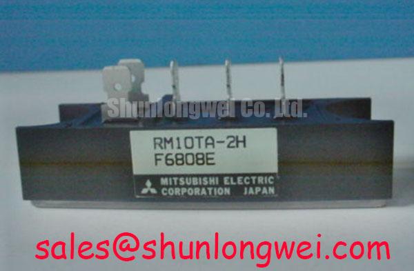
With power removed and terminals isolated, first compare the cold diode readings across each rectifier path and confirm that no path shows an unexpected low resistance in both polarities. The RM10TA-2H from Mitsubishi Electric is a three-phase diode module rated at 1600 V repetitive peak reverse voltage and a specified 10 A average rectified output current, according to the official datasheet specification. Its stated operating junction temperature range is −40°C to +150°C.
| Official Datasheet Parameter | Rating |
|---|---|
| Repetitive peak reverse voltage, VRRM | 1600 V |
| Non-repetitive peak reverse voltage, VRSM | 1700 V |
| Average rectified output current, IO | 10 A under the specified conditions |
| Surge forward current, IFSM | 400 A, 60 Hz, one cycle |
| Fusing I²t | 670 A²s at 8.3 ms |
| Isolation voltage, main terminals to case | 2500 V AC for one minute |
| Junction to case thermal resistance | 0.55°C/W per diode |
In a high voltage three-phase motor solid state soft starter, the RM10TA-2H can be evaluated as part of the rectification and power interface path rather than treated as a phase angle controlled device itself. Before commissioning, verify the marked terminal arrangement against the equipment schematic and measure each diode junction with a diode test function. Comparable forward readings between corresponding paths are a useful cold state reference; materially inconsistent readings require investigation with the module disconnected from surrounding circuitry.
Phase angle control is normally determined by the associated controlled semiconductor stage and controller timing. A motor soft starter may reduce locked rotor current from the multiple of rated current associated with direct line starting, but the actual current profile is system determined by motor characteristics, firing control, line impedance, bypass arrangement, and load torque. The RM10TA-2H official 10 A average output current rating must be checked against the rectifier duty, measured enclosure temperature, and heatsink conditions rather than against motor nameplate current alone.
💡 Bench Tip: Record cold diode test readings and terminal orientation before reconnecting control wiring, using ESD controlled handling and an isolated meter.
Design Consideration: reverse recovery behavior, snubber response, and radiated noise are properties of the complete commutation loop. Use an oscilloscope to compare phase voltages and current waveforms with a known good path, then verify that repetitive voltage peaks remain within the 1600 V VRRM rating and that non-repetitive events remain within the 1700 V VRSM rating. For broader three-phase switching context, see The 1200 V CoolSiC™ MOSFET Advantage in Three.
Field Diagnostics & Commissioning: Semiconductor Protection Fuse Selection in RM10TA-2H Topologies
The official fusing capability figure for the RM10TA-2H is 670 A²s at 8.3 ms. This value supports a coordination review, but it is not by itself a fuse selection instruction. The fuse manufacturer’s total clearing I²t, prospective fault current, available fault duration, ambient conditions, and coordination with contactors or upstream protection must all be reviewed by the system designer.
For incoming inspection or repair work, document the installed semiconductor fuse part number, its time current curve, and its stated pre arcing and total clearing I²t values. Compare these documented values with the module’s official I²t rating and the equipment protection study. A dead short event can involve source impedance and multiple parallel fault paths, so no component page can establish a zero damage outcome without the complete system data.
Design Consideration: inspect terminal faces, busbar flatness, and hardware engagement before energization. Loose or unevenly loaded connections can add resistance and localized heating, which can complicate interpretation of current and fuse performance. Where an alternative rectifier family is being technically reviewed, RM500CZ-M should be compared only against its own published electrical, mechanical, and thermal specifications.
Assembly Integrity & Layout Architecture: Implementing AC Input Transient Overvoltage Clamping for RM10TA-2H
The voltage boundary for this module is clear: 1600 V repetitive and 1700 V non-repetitive peak reverse voltage. In a soft starter cabinet, technicians should capture line-side transients at the actual installation point before deciding whether an existing MOV network, RC suppression network, or upstream protection arrangement is adequate. Clamp selection depends on the supply system, measured surge environment, stored energy, coordination with upstream protection, and the allowable voltage at the rectifier terminals.
Design Consideration: keep high-current commutation paths compact and mechanically secure to reduce parasitic inductance that can contribute to transient overshoot. Verify peak voltage at the module terminals during switching and abnormal line events, rather than inferring performance from a schematic alone. IEC 61000-4-5 system testing can inform equipment-level surge assessment, but it does not constitute a standalone compliance claim for this diode module.
When a design includes a separate higher-current rectification position or complementary power stage, the published characteristics of RM100HA-20F can be reviewed independently. Mitsubishi Electric’s power semiconductor application information is also useful background for assessing power-stage interactions, without implying that CSTBT technology is used inside the RM10TA-2H diode module.
RM10TA-2H Circuit Protection & Reliability: Calibrating Uniform Heatsink Contact Pressure
Check the mounting surface for burrs, discoloration, old compound residue, and distortion before fitting the RM10TA-2H. The official junction-to-case thermal resistance is 0.55°C/W per diode; this describes the specified internal thermal path and does not include the interface material, heatsink, airflow, or cabinet temperature. A thin, continuous thermal interface layer and uniform fastening help the external assembly approach its intended thermal performance.
Use the mounting hardware, tightening sequence, and torque specified by the original equipment mechanical documentation or the applicable Mitsubishi package drawing. Do not infer a torque value from another module style. After tightening, inspect for even compound displacement around the mounting region and confirm that the package remains flat against the heatsink.
⚡ Safety Interlock Note: Isolate and verify discharge of all stored energy before loosening power terminals or removing the module from the heatsink.
The stated 2500 V AC isolation voltage for one minute applies between the main terminals and case under the official test condition. During service, insulation testing must follow the equipment manufacturer’s procedure because connected control boards, surge suppressors, and sensing circuits can affect the test result. No unsupported life, altitude, cosmic ray, or field failure prediction should be derived from the published electrical ratings alone.