

Content last revised on September 16, 2026
RM20HA-20F Operational Boundaries: Junction-to-Heatsink Heat Dissipation
With the equipment isolated and discharged, first inspect the RM20HA-20F case, terminals, mounting faces, and connected busbars for looseness, heat discoloration, cracked insulation, or distorted hardware; then compare directional diode readings across the accessible power terminals with the original circuit documentation and a known-good path where available.
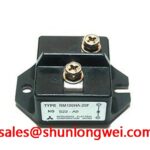
The RM20HA-20F is a Mitsubishi Electric diode module with a published 1000 V repetitive peak reverse-voltage rating and 20 A average forward-current rating. Its factory ratings define the electrical boundary of the module itself, not the guaranteed performance of the complete induction-heating power supply. Before replacing a module in a medium-frequency induction melting or hardening furnace, technicians should confirm the terminal arrangement, heat-transfer interface, circuit position, upstream protection, and measured operating conditions against the removed unit and equipment documentation.
| Official Datasheet Specification | RM20HA-20F Value |
|---|---|
| Repetitive Peak Reverse Voltage, Vrrm | 1000 V |
| Average Forward Current, If av | 20 A |
| Surge Forward Current, Ifsm | 400 A |
| Reverse Recovery Time, trr | 0.8 microseconds |
| Junction Temperature, Tj | minus 40 degrees C to plus 150 degrees C |
| Isolation Voltage, Viso | 2500 V |
Start the heat-path check at the module mounting surface. Remove residual old thermal interface material, inspect the heatsink for raised burrs and corrosion, and check that the contact area is flat and clean before seating the replacement. Uneven pressure can leave part of the base poorly coupled to the heatsink, while excessive mechanical force can damage the package or compromise isolation. The published information supplied for this model does not specify thermal resistance, mounting-hole size, bolt torque, baseplate construction, package dimensions, or a thermal-paste thickness. These values must therefore be taken from the original Mitsubishi Electric documentation and the equipment mechanical drawing rather than inferred from the current rating.
Field Alert: Tighten mounting hardware to the equipment manufacturer’s specified sequence and torque only after the module sits flat on an evenly spread, thin thermal interface layer.
The minus 40 degrees C to plus 150 degrees C junction-temperature range is an Official Datasheet Specification, but it is not a permission to operate continuously at the upper endpoint. As a Design Consideration, the service engineer should verify heatsink airflow or coolant condition, fan operation, thermal-interface coverage, and terminal joint resistance under the actual load cycle. A localized hot area on the heatsink, a recurring fuse operation, or unequal temperature between parallel current paths may indicate that the assembly needs broader inspection rather than that the diode module alone is at fault.
Fuse coordination also requires the fuse manufacturer’s time-current and I squared t data, together with the measured fault environment. No fuse I squared t value has been provided as an Official Specification for the RM20HA-20F. Do not assign a fuse solely from the module’s 20 A average-current rating or its 400 A surge-current rating. The protection device must be assessed against prospective fault current, conductor capability, upstream disconnect behavior, and the actual rectifier topology.
Benchtop Waveform Tuning: Coordinating Spark Gaps, MOVs, and Snubbers
At the bench, inspect the protection network before energizing a repaired power section. Check MOV bodies for cracking or discoloration, verify that surge-protection wiring is secure, and inspect RC snubber parts for open connections or damaged capacitors. Spark gaps, MOVs, and snubbers belong to the equipment-level overvoltage-control network; they are not intrinsic published features of the RM20HA-20F. Their selection and placement are system-determined and should be verified from the furnace power-supply schematic and observed switching waveforms.
The module’s 0.8 microseconds reverse-recovery time is an Official Datasheet Specification. During commutation, stored charge removal and circuit inductance can contribute to transient stress. The physical mechanism is described in this technical reference on diode reverse recovery. As a Design Consideration, minimize parasitic loop inductance and verify peak voltage against the 1000 V Vrrm boundary using suitable high-voltage differential measurement methods during controlled testing.
Where the wider cabinet includes an upstream or complementary rectifier stage, technicians may also document the ratings and connection pattern of parts such as RM100HA-20F. This is a neutral reference for circuit review, not a statement of interchangeability. Current rating, voltage rating, terminal geometry, thermal behavior, and the original equipment design must all be verified before any part is considered for a repair.
Medium-frequency induction melting and hardening equipment is a relevant compatibility-evaluation example because its power conversion section can impose repetitive commutation and high stored energy. It should not be assumed that one protection arrangement applies across furnaces. Designers should validate protection behavior at the actual mains condition, transformer configuration, load state, and switching sequence.
RM20HA-20F Operational Boundaries: Diode Current-Path Checks
The RM20HA-20F is specified here as a diode module and has no published gate terminal, gate-firing pulse requirement, holding-current specification, or multi-pulse firing function. Gate pulse rise time, back-porch current, and localized gate-hotspot analysis therefore do not apply to this module. Applying thyristor gate-drive assumptions to a diode replacement can lead to incorrect troubleshooting and unnecessary circuit changes.
The relevant service check is the diode current path. With power removed and energy-storage capacitors safely discharged, inspect the terminal hardware, busbar contact faces, and conductor routing for unequal current paths or signs of heating. For systems that use multiple diode paths in parallel, current sharing is a Design Consideration governed by the complete assembly: path resistance, thermal coupling, conductor symmetry, and switching conditions all matter. No positive temperature-coefficient behavior, parallel-sharing capability, or matched-device requirement has been supplied as an Official Specification for this model.
For a repair review involving a different module family, RM500CZ-M can be consulted as a separate product reference. It must not be treated as a direct replacement for the RM20HA-20F without a complete electrical, mechanical, thermal, and circuit-function comparison. The original module position and equipment documentation remain the controlling references.
RM20HA-20F Operational Boundaries: Surge-Current Rating and Test Conditions
The Official Datasheet Specification provided for the RM20HA-20F lists a 400 A surge forward current, Ifsm. It does not provide the associated waveform duration, sinusoidal half-cycle condition, starting junction temperature, repetition allowance, or fuse coordination value. A technician should not relabel this rating as a 10 ms half-cycle capability without the original manufacturer datasheet test conditions.
After an overcurrent event, inspect the complete rectifier section before reapplying reverse voltage. Check semiconductor connections, fuses, MOVs, snubbers, transformer secondary wiring, and the load-side circuit for damage or abnormal resistance. A diode reading alone cannot establish that all components survived the same event. Controlled recommissioning should include monitoring of supply voltage, current behavior, heatsink condition, and waveform overshoot, with acceptance limits defined by the system engineer.
The 2500 V isolation-voltage rating is an Official Datasheet Specification for the module, while insulation performance in the installed assembly also depends on mounting cleanliness, creepage paths, enclosure condition, wiring, and contamination. For structured comparison of voltage, current, thermal, package, and application constraints, use the Power Semiconductor Selection Guide alongside the original equipment records.


