


Content last revised on October 1, 2026
Preventing Spurious Faults: Saturable Reactor and Snubber Sizing Guidelines for RM50HA-24F
| Manufacturer | Mitsubishi Electric |
|---|---|
| Product category | Diode Module |
| Model | RM50HA-24F |
| Voltage rating | 1200 V |
| Rated current | 50 A |
| Package | Diode Module |
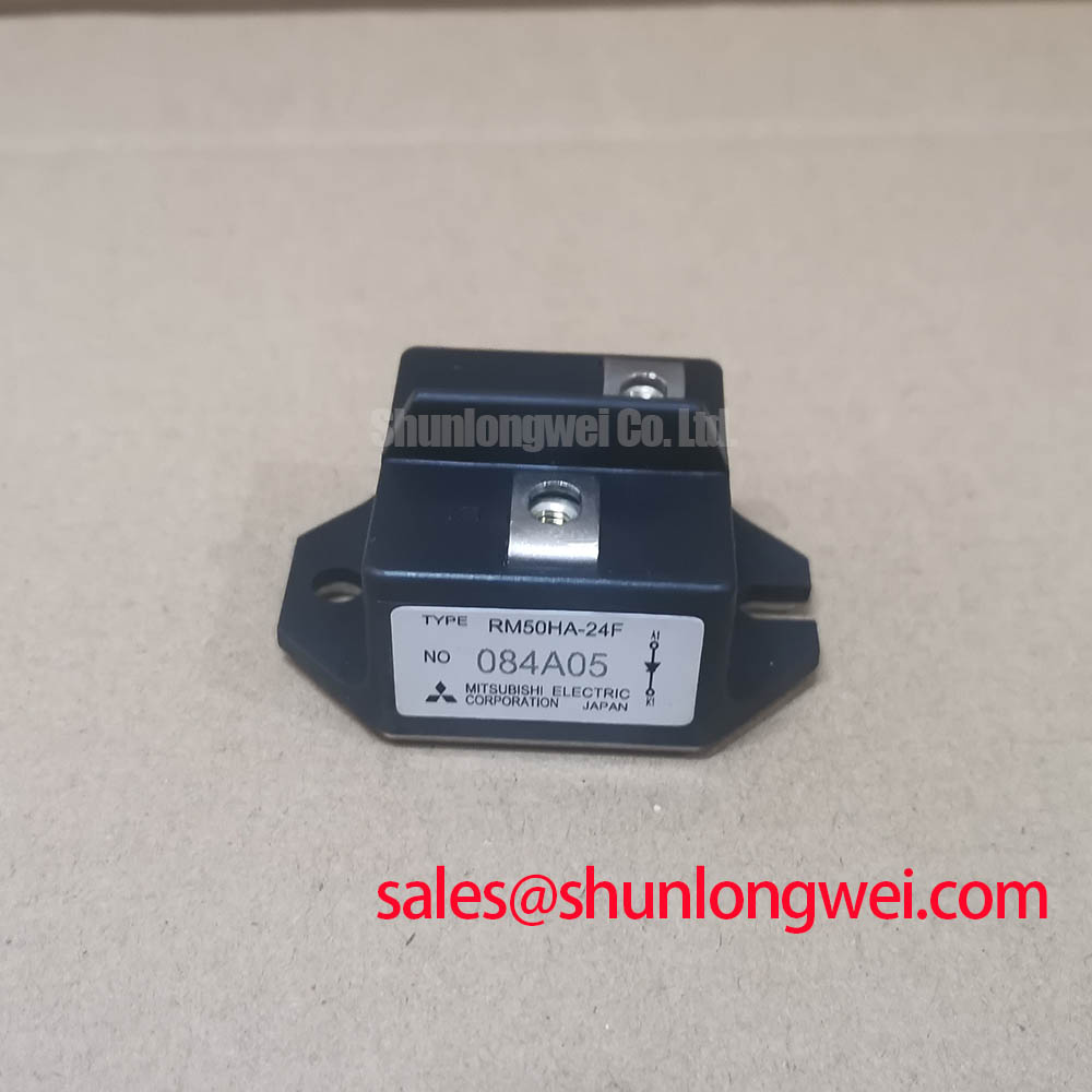
Measure the diode module terminals with the DC link isolated, then compare the cold-state impedance pattern with a known-good unit before disturbing the snubber or saturable reactor wiring. The RM50HA-24F is identified as a Mitsubishi Electric diode module, so the replacement assessment must begin with the original circuit topology, terminal markings, and the equipment documentation rather than with a generic IGBT gate-drive assumption.
In a grid-tied Static Var Compensator or thyristor-switched capacitor cabinet, inspect the complete commutation path for loose busbar joints, discolored terminal hardware, cracked insulation, and unexpected conductor movement. A saturable reactor is selected by the system designer to limit the rate of current rise during the relevant transient, while an RC snubber is evaluated for suppression of voltage ringing and unwanted diode stress. The values of the snubber resistor, capacitor, and reactor must be determined from the measured switching waveform, system voltage, parasitic inductance, and the original protection design.
Use the manufacturer’s specified fuse coordination and I²t information when checking semiconductor protection. Do not substitute a fuse solely because its continuous current appears similar. Confirm its clearing behavior against the prospective fault current and the protection table associated with the installed circuit. Terminal orientation and polarity must match the original assembly, with busbar surfaces clean, flat, and free from burrs.
RM50HA-24F Circuit Protection and Commutation Turn-Off Voltage
Capture the commutation voltage and current at the diode terminals with a properly rated differential probe and current measurement method while the cabinet remains within its approved test procedure. A reverse-recovery event can produce a transient peak that is influenced by wiring inductance, source impedance, load current, temperature, and the surrounding capacitor or reactor network.
The relevant diode review should include reverse-recovery peak current, recovery time, and the shape of the recovery waveform where those values are available in the applicable Mitsubishi Electric documentation. Do not infer soft-recovery performance from a resistance check. Compare the measured waveform with the original unit under equivalent operating conditions, then review whether the snubber, fuse, busbar layout, and commutation components are imposing abnormal stress.
For manufacturer context, the Mitsubishi Electric Diode Modules Lineup provides the appropriate product-family reference. When evaluating a related replacement path, engineers may also compare the electrical and mechanical requirements of RM50DZ-24, but substitution remains dependent on verified voltage, current, package, terminal, thermal, and protection compatibility.
RM50HA-24F Thermal-Electrical Optimization: Junction-to-Heatsink Heat Dissipation
Remove the module only after confirming isolation, discharge, and zero-energy conditions, then inspect the mounting face and heatsink contact area for uneven marks, dried compound, contamination, or distortion. The RM50HA-24F package is specified as a diode module; its usable thermal performance depends on the complete assembly formed by the module base, interface material, heatsink, clamping hardware, airflow, and electrical duty.
Clean both mating surfaces using a process approved for the equipment and apply the thermal interface material as a uniform thin layer suitable for the surface finish. The mounting sequence should follow the manufacturer’s mechanical instructions, including the specified tightening order and torque for the actual hardware. Do not use a guessed torque value because excessive pressure can distort the package, while insufficient pressure can create local thermal resistance.
During commissioning, monitor heatsink temperature, terminal temperature, load current, and the switching waveform together. A thermal rise that differs from the previous installation may result from contact pressure, compound distribution, airflow, busbar heating, or an altered electrical duty cycle. The system engineer should verify the junction-to-case and case-to-heatsink assumptions against the applicable thermal data before approving continuous operation.
Field Alert: Keep the module electrically isolated during mechanical work and apply only the mounting torque specified for the installed fastener and assembly.
Benchtop Waveform Tuning: Mitigating Stress During Non-Repetitive Surge Current Testing on RM50HA-24F
Check the recorded current waveform for the complete sinusoidal half-cycle and inspect the first abnormal pulse before applying repeated surge testing. The non-repetitive surge on-state current rating, including the specified 10 ms half-cycle condition where applicable to the original documentation, must be treated as a controlled short-duration limit rather than as a normal operating current.
Verify the initial junction-temperature condition, cooling path, fuse coordination, and reverse-voltage reapplication sequence before any bench test. A diode that survives one current pulse may still experience accumulated thermal or commutation stress when the test is repeated. The test plan should therefore define pulse count, recovery interval, measurement bandwidth, probe placement, and stop criteria from the equipment safety procedure and the applicable factory data.
For broader switching physics and thermal interpretation, consult The Ultimate IGBT Knowledge Base as a technical reference, while keeping the RM50HA-24F assessment focused on its diode-module function. Before returning a grid-tied SVC or thyristor-switched capacitor system to service, verify polarity, terminal tightness, insulation condition, cooling contact, fuse coordination, and the absence of excessive reverse-voltage overshoot in the measured waveform.