
Content last revised on October 19, 2026
RM100DZ-2H Circuit Protection & Reliability: Assessing Forward Current and Temperature Dependence
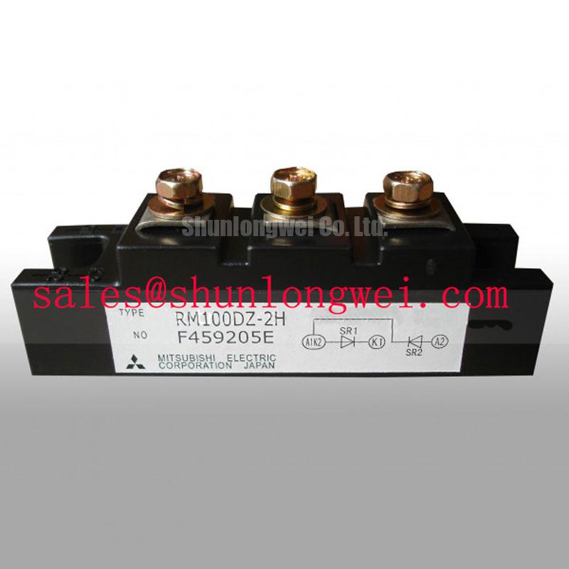
When a rectifier leg shows uneven current sharing or repeated fuse operation, first identify the semiconductor topology before applying a gate-drive diagnostic. The RM100DZ-2H is a Mitsubishi Electric dual diode module with a common-cathode DZ configuration; it is not an IGBT or thyristor and therefore has no gate trigger current, gate firing pulse, Miller plateau, or back-porch holding-current requirement. Any test procedure based on gate pulse rise time or multi-pulse firing is inappropriate for this part.
The relevant protection review is the current path through each diode element, the commutation loop, the external fuse, and the DC output conductors. The official repetitive peak reverse voltage is 1200 V VRRM, while the official average forward current is 100 A IF(AV). These values identify the device class, but system engineers still need to assess line waveform, duty cycle, cooling, overload duration, and transient conditions in the complete rectifier.
For a high-current green hydrogen electrolyzer DC power rectifier, map the common-cathode connection and each anode terminal against the original schematic before energizing the replacement. Confirm that the external fuse coordination uses the applicable fuse manufacturer’s total clearing I²t data and the diode manufacturer’s withstand data under the relevant operating conditions. The fuse must interrupt the fault energy before semiconductor damage develops; its suitability cannot be established from the diode current rating alone.
Temperature dependence should be assessed through forward-voltage balance and heatsink temperature at the actual load. If one phase leg runs hotter, inspect conductor symmetry, terminal contact, thermal interface coverage, and current sharing rather than attributing the result to a trigger-current problem. The 2500 V AC isolation voltage for one minute is an official specification for the insulated baseplate isolation system and should be considered alongside the enclosure, heatsink, creepage, and test procedure.
For broader power-stage integration practices, the IGBT Design & Integration reference is useful for busbar arrangement, thermal verification, and switching-loop evaluation, although its gate-drive guidance does not change the passive diode function of this module.
RM100DZ-2H Operational Boundaries: Evaluating RC Snubber Networks to Control Voltage Stress
RC snubber selection for the RM100DZ-2H should begin with the measured commutation waveform, not with a generic capacitor or resistor value. During turn-off of an upstream controlled device or during diode recovery, stray inductance can produce a voltage excursion across the diode. The design objective is to control ringing and unwanted voltage stress while keeping snubber loss and thermal loading within the system budget.
The 1200 V VRRM rating provides the official reverse-voltage boundary for repetitive operation, but it does not define the permissible peak of every installation transient. Place the voltage probe directly across the relevant diode terminals and compare the waveform at light load, rated load, and the most demanding switching condition. The measured ringing frequency and damping response can then guide selection of an RC network by the system designer.
A saturable reactor may be evaluated in series with the power path when the rectifier topology produces a severe current transition. Its effect should be checked for conduction loss, recovery behavior, and mechanical installation constraints. The same evaluation applies to a metal-oxide varistor used as a coordinated surge-absorption element: its clamping behavior, energy rating, and coordination with upstream protection must be selected for the complete DC rectifier rather than inferred from the diode module label.
The common-cathode arrangement can simplify a two-phase rectifier or freewheeling diode pair, but it also makes terminal identification and busbar symmetry important. Keep the high-current paths short and physically balanced where practical, then verify the voltage across each diode with an appropriately rated isolated differential probe. Mitsubishi Electric’s Bootstrap Circuit Design note addresses bootstrap systems rather than this diode module, yet it provides useful context for separating control-side assumptions from power-device behavior.
The RM100HA-20F may be reviewed as a separate Mitsubishi Electric power-module option when the equipment architecture requires a different device class or configuration. It should be compared against the original circuit requirements rather than treated as an automatic substitute.
Transient Dynamics & Electrical Design: Junction-to-Heatsink Heat Dissipation in the RM100DZ-2H
Thermal verification of the RM100DZ-2H depends on uniform heat transfer from each diode element into the heatsink. The official junction-to-case thermal resistance is 0.28 °C/W per element. Use this value as the semiconductor-to-case portion of the thermal assessment, then add the thermal interface and heatsink contributions defined by the installation.
Before mounting, inspect the heatsink contact surface for burrs, contamination, and local distortion. Apply the selected thermal interface material as a continuous, even layer suited to the surface finish; the final interface thickness and coverage should be controlled by the system assembly process rather than assumed from a generic module rule. Tighten the mounting hardware progressively and evenly according to the applicable Mitsubishi Electric mechanical instructions.
Safety interlock note: Isolate the rectifier, discharge stored energy, and verify absence of hazardous voltage before touching terminals, the heatsink, or any snubber connection.
After installation, check that the module baseplate sits flat without rocking and that both diode paths show comparable thermal behavior under balanced loading. A temperature difference may arise from conductor resistance, airflow, thermal-interface variation, or unequal phase loading, so correlate thermal-camera observations with electrical current measurements.
For a bidirectional DC to DC battery charge and discharge stage connected to the rectifier, evaluate thermal cycling across both power-flow directions. The module’s 100 A IF(AV) rating is an official average forward-current specification, not a complete lifetime prediction for a battery system. Designers should verify peak junction temperature, transient thermal impedance, enclosure airflow, and cooling response during the real charge, discharge, and regeneration sequence.
The RM500HA-H can be considered as a separate upstream or complementary power-stage device where the system topology calls for a higher-current module class. Mitsubishi Electric’s Diode Modules Lineup provides additional manufacturer-level context for comparing diode-module configurations.