


Content last revised on October 1, 2026
Transient Dynamics and Electrical Design: Fuse Coordination for RM100DZ-H
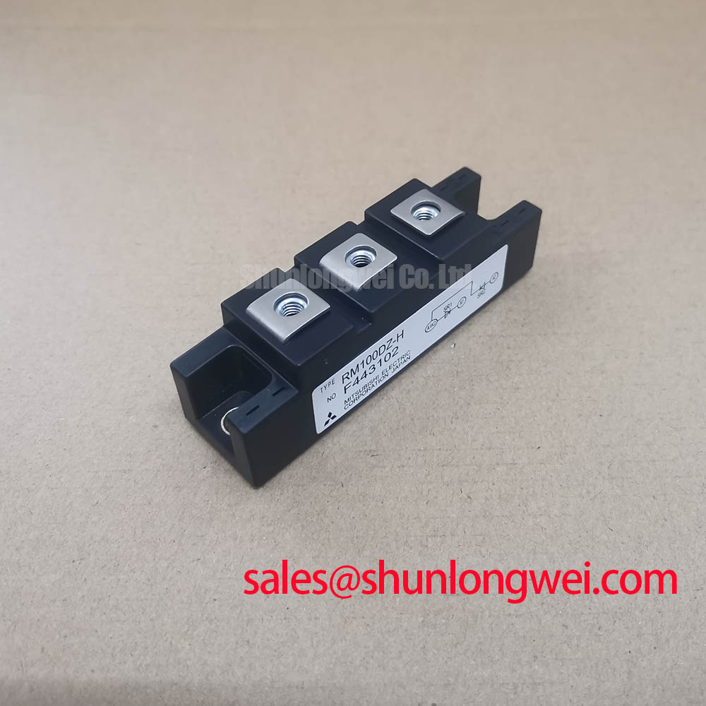
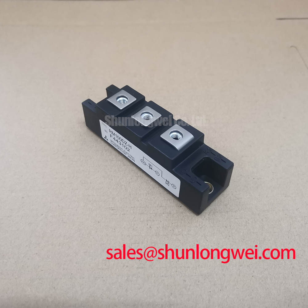
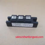
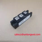
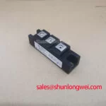
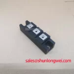
RM100DZ-H | Mitsubishi Electric | Diode Module | Rectifier component. Numerical voltage, current, surge, thermal and mounting ratings are not established by the supplied product data.
Measure the isolated rectifier path and inspect the fuse after a short-circuit trip before reconnecting an RM100DZ-H module. Record the fault location, the fuse identification and any visible damage at the module terminals. A fuse that has opened does not, by itself, establish that the diode remained within its surge limit.
For fuse coordination, compare the selected fuse’s total clearing I²t with the diode’s applicable surge and I²t limits at the stated test conditions. The supplied product data do not establish numerical limits for RM100DZ-H, so a claim that a particular fuse will prevent module damage would be unsupported. As a Design Consideration, the system engineer should also account for prospective fault current, DC-link energy and the time required for the protection device to clear. Mitsubishi Electric’s diode module lineup provides manufacturer context for the device category, but it is not a substitute for this model’s electrical limits.
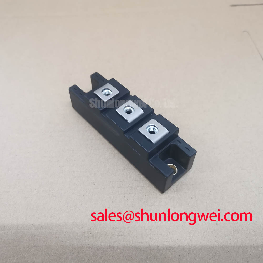
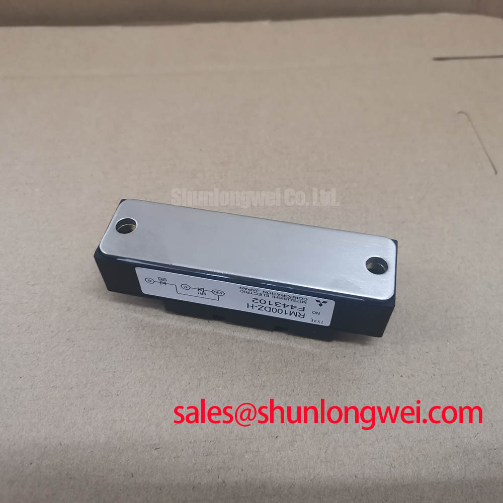
Trace the terminal connections against the equipment schematic rather than assuming that a visually similar module has the same circuit arrangement. In a high-current green hydrogen electrolyzer DC rectifier, compatibility assessment should include the rectifier topology, terminal geometry and fault-protection scheme. The RM10TA-H can be examined as a separate selection candidate, but its ratings, connections and mounting interface require an independent comparison; it is not an established drop-in replacement.
Field Diagnostics and Commissioning: Reactor and Snubber Checks in RM100DZ-H Topologies
Capture the diode terminal voltage and branch current during a controlled commissioning test if repeated trips occur at energization. Compare the traces with a known-good branch and check for reverse-voltage overshoot, current concentration or unexpected ringing. Those observations can guide inspection, but no single waveform feature proves that the module caused the trip.
A diode module has no gate terminal to turn on spuriously through a Miller plateau. In a phase-controlled rectifier, gate-drive timing belongs to the associated thyristors, not to RM100DZ-H. Snubbers and series reactors, where present in the equipment design, should therefore be assessed against the actual commutation path. As a Design Consideration, a snubber may moderate voltage transients and a reactor may influence current rise; their values depend on measured circuit behavior and the limits of every affected component. Do not select either from the module name alone.
Inspect snubber connections for looseness or heat damage, then compare capacitor and resistor measurements with the equipment drawing. Check reactor wiring and look for branch-to-branch differences before changing components. If controlled switches elsewhere in the rectifier show timing anomalies, Precision Gate Drive Design is relevant to that separate drive circuit; it does not imply that this diode module needs gate-drive adjustment.
Benchtop Thermal Checks: Heatsink Contact for RM100DZ-H
Inspect the heatsink contact area when one rectifier branch runs hotter than its peers under comparable load. Look for uneven thermal-interface coverage, debris, damaged mating surfaces and inconsistent fastener seating. Record case or heatsink temperatures at repeatable measurement points, since a temperature difference alone does not isolate the cause to the semiconductor.
Thermal assessment needs the model-specific junction-to-case resistance, permitted junction temperature and the operating loss estimate. Numerical values for those parameters are not established in the supplied product data. As a Design Consideration, the system engineer should evaluate the complete heat path under the intended current waveform, including the interface and heatsink, rather than treating a cool heatsink reading as proof of adequate junction margin.
Spread thermal-interface material evenly and use the applicable mounting instructions to determine fastening order and torque; an unverified torque figure risks a misleading assembly check. Polyphenylene sulfide is described as a high-temperature engineering plastic in this materials reference, but the supplied product data do not identify it as a material in RM100DZ-H. Baseplate contact and terminal condition can be inspected without making assumptions about the module’s internal construction.
Surge Duty and Repeated Starts: Evaluating RM100DZ-H
Log branch current during startup and fault recovery when a module is suspected of experiencing repeated surge stress. Compare the measured pulse shape and starting thermal condition with the model-specific surge-current test conditions. The supplied product data do not establish an ITSM value for RM100DZ-H; assigning one from another diode module would make the assessment unreliable.
Non-repetitive surge capability should not be treated as permission for repeated operation at that limit. As a Design Consideration, evaluate the interval between events, the estimated junction temperature before each event and the reverse voltage reapplied after current falls. Protection settings and operating limits must be validated against the equipment waveform and the applicable module specifications.
💡 Pro Tip: Keep the rectifier connection layout consistent between parallel paths and verify current sharing under load before attributing a recurring hot branch to the module. If a controlled test still shows unequal current, inspect connections, cooling contact and upstream control behavior as separate possible contributors.