Content last revised on September 20, 2026
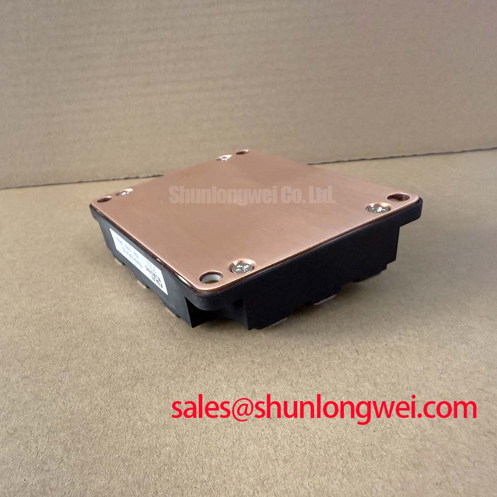
Assembly Integrity & Layout Architecture: Implementing Multi-Module Parallel Current Sharing for 7MBP50RJ120
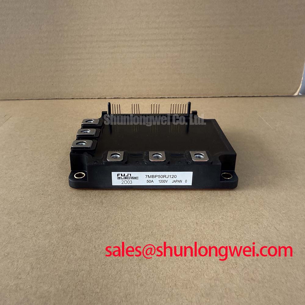
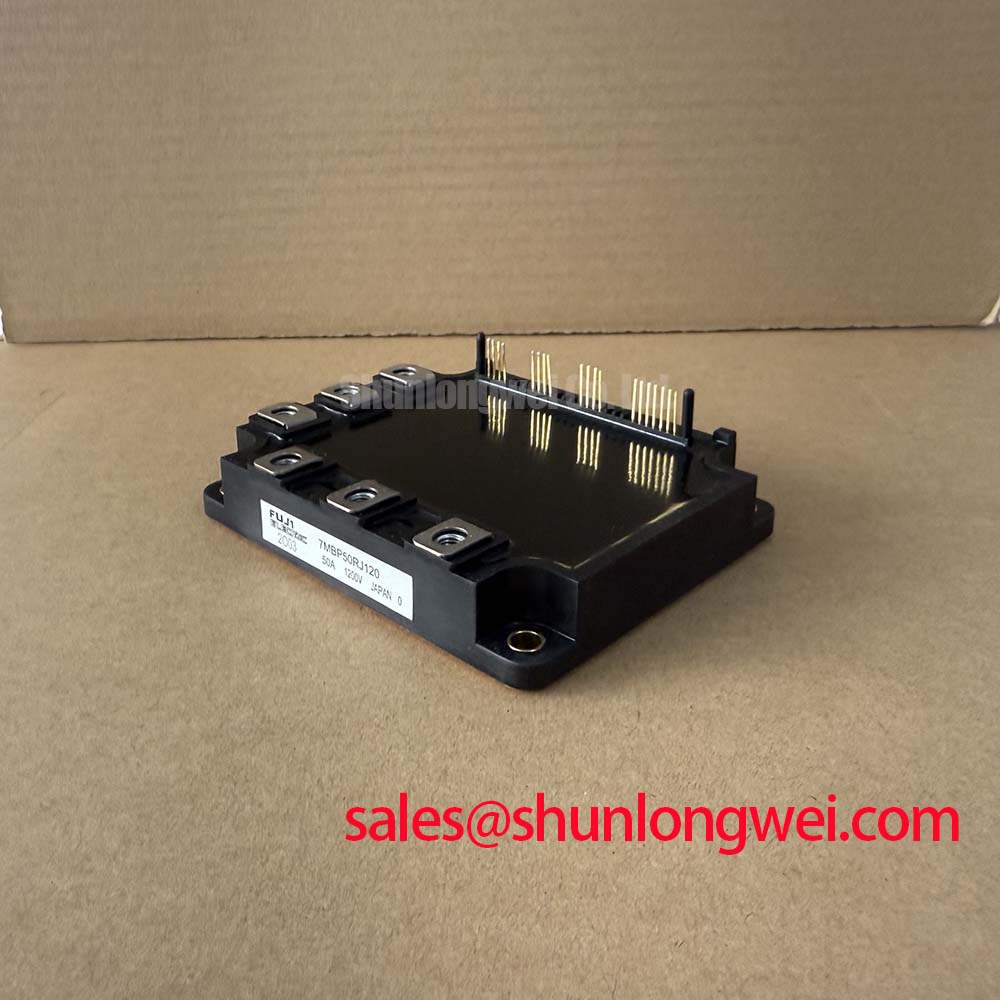
Parallel use of 7MBP50RJ120 modules demands evidence-based matching of the complete electrical and thermal paths rather than a comparison of nominal current ratings alone. The specified 50 A rated collector current applies to the individual module under the datasheet's specified conditions. When a converter uses parallel power paths, the system engineer must determine the actual current allocation under its operating temperature, modulation method, switching conditions, and cooling constraints.
A Design Consideration is that the positive temperature coefficient associated with IGBT on-state behavior can support steady-state current sharing between appropriately matched devices. It does not guarantee dynamic sharing during switching. Small differences in gate-loop inductance, individual gate resistance, driver propagation delay, power-busbar length, or heatsink contact can produce unequal transient current. The resulting imbalance is most visible during switching events, where the device that changes state first can briefly carry a disproportionate load.
Begin with physical symmetry. Place modules so corresponding DC-link and phase-current paths have comparable geometry. Route each gate-drive pair as a compact forward-and-return loop, keeping the driver reference intentionally associated with the relevant emitter reference defined by the equipment design. Avoid allowing one gate loop to cross a high-current commutation path while another does not. The same discipline applies to desaturation sensing and fault-return routing, because a protection circuit that observes one module differently from another may react inconsistently.
During commissioning, capture each parallel branch current with measurement methods suitable for the expected bandwidth and compare switching timing across equivalent devices. A difference can indicate several possible conditions: an unmatched gate path, a nonuniform power connection, driver asymmetry, a degraded connection, or unequal thermal coupling. Inspect the evidence before changing component values. An arbitrary gate-resistor change can shift loss, overshoot, and protection timing in a way that conceals the original problem.
Terminal clearance and creepage must be assessed as part of the installed converter, not inferred from the module rating alone. The required distances depend on the final voltage environment, pollution degree, enclosure, material group, altitude, contamination exposure, and the applicable equipment standard. Clean conductive debris, residue, damaged insulation barriers, and loose hardware can undermine an otherwise correct layout. Check the original fastening method for all current-carrying busbars and confirm that vibration restraint remains effective after service.
Pro Tip: Keep parallel DC-link and gate-drive paths geometrically symmetric, then verify current balance and peak voltage with measured switching waveforms before approving the assembly.
Where a replacement review also considers a related module, 7MBR50SB120-01 can be examined as a same-class reference point, but mechanical, internal topology, terminal allocation, drive requirements, and protection compatibility must be verified from the applicable documentation rather than assumed from a similar rating.
Preventing Spurious Faults: High-Frequency Common-Mode Bearing Current Guidelines for 7MBP50RJ120
Confirm phase-terminal identity and the intended motor-cable landing points against the original inverter documentation before energizing a serviced system using 7MBP50RJ120. A phase connection error, a disturbed shield termination, or a changed cable route can create symptoms that resemble a module or driver fault. Inspect the DC-link connections, motor terminals, protective-earth path, and control reference before interpreting waveform behavior.
Long motor leads behave as transmission lines at switching edges. When cable impedance and motor termination do not match, reflected waves can raise the motor-terminal voltage substantially above the initially launched step. In some conditions, a reflected event can approach twice the DC-link voltage at the remote terminal. That behavior is a system-level electrical phenomenon, not an official voltage rating or a predicted outcome for this module. It should be investigated by measuring at appropriate points in the actual installation with a measurement arrangement rated for the observed voltage and frequency content.
High-frequency common-mode voltage can also couple through motor parasitic capacitances and bearing structures. Bearing-current observations should not be assigned to a single source without measurement. Cable length, shield termination, motor construction, inverter switching behavior, grounding architecture, output filtering, and external conductive paths can all affect the result. Inspect for continuity where intended, unexpected shield contact, and changes made during cable replacement or cabinet repair.
A Design Consideration is to use the output filter or choke approach selected for the actual motor lead, inverter topology, switching behavior, and applicable motor insulation requirements. Designers should verify whether the installed filter is compatible with the switching waveform and current demand rather than adding a generic network. An output filter can modify terminal stress, common-mode behavior, control-loop response, and loss distribution, so it belongs in a measured system validation process.
When a converter reports intermittent overcurrent, ground-related, or drive faults after cable work, collect synchronized DC-link, phase-voltage, gate-drive, and fault-status evidence where safely practical. Compare the event with a known-good installation or the documented commissioning waveform. A repeated fault at the same switching edge may indicate a layout or impedance issue, while an irregular event may require inspection of connectors, vibration exposure, cable damage, grounding, and control timing.
Fastening quality matters because a busbar that remains electrically connected at rest can behave differently under vibration and pulsed current. Review the specified hardware, washer stack, contact surfaces, and tightening procedure supplied by the equipment manufacturer. Do not substitute an assumed torque value for the assembly requirement. The module's 1200 V rating should be considered alongside the complete insulation system, including clearances, creepage paths, cable insulation, barriers, and enclosure conditions.
For a broader technical framework covering inverter reliability, waveform assessment, and component selection boundaries, consult the Power Electronics Masterclass.
Transient Dynamics & Electrical Design: High-Altitude Cosmic Ray Induced SEB Evaluation for 7MBP50RJ120
The 1200 V specified voltage rating of 7MBP50RJ120 is the starting point for electrical review, not a universal operating prescription. Before an installation at elevated altitude is approved, establish the actual DC-link voltage range, measured switching overshoot, regenerative operating conditions, protection response, cooling state, and the insulation requirements of the complete equipment. Those conditions determine the relevant operating margin.
Cosmic-ray and terrestrial-neutron effects, including single-event burnout discussions, are high-risk reliability subjects that require manufacturer-specific qualification data or authoritative test evidence before a numerical failure-rate claim can be made. No FIT rate, service-life projection, altitude threshold, or burnout multiplier should be inferred for this module from its voltage and current ratings. The official parameters provided here do not establish a cosmic-ray qualification result.
A Design Consideration is that an elevated installation can increase the need for careful assessment of both insulation coordination and semiconductor voltage stress. Reduced air density may affect external clearance requirements under applicable standards, while site elevation may also be relevant to a system-level reliability analysis. The responsible equipment designer should apply the governing standard, environmental classification, and manufacturer documentation for the full assembly. Do not treat a generic altitude rule as a substitute for that assessment.
For a converter that operates near a high DC-link condition, evaluate voltage stress using representative switching tests rather than nominal bus voltage alone. Turn-off overshoot reflects the interaction of commutation current, busbar inductance, DC-link capacitor placement, diode recovery behavior, gate-drive timing, and measurement setup. Minimize parasitic commutation-loop inductance to suppress inductive overshoot, then verify peak margins against DC-link voltage during switching tests. This is an Engineering Recommendation for the inverter assembly, not an official construction specification of 7MBP50RJ120.
The freewheel path should be examined as part of that waveform review. Reverse-recovery behavior can affect current commutation and high-frequency emissions, but the reverse-recovery softness factor is not specified in the provided official data for this product. It must not be assigned a numerical value or used to claim a specific EMI outcome. Oscilloscope evidence can show whether the recovery interval coincides with ringing, excessive voltage excursion, or a protection response in the actual inverter.
For electric material-handling and forklift low-voltage traction systems, this module may be evaluated where the original electrical architecture, voltage class, cooling arrangement, and control interface match the equipment requirement. Battery voltage alone does not establish suitability. Charging conditions, regenerative braking, wiring inductance, fault handling, and installed motor-cable geometry must all be reviewed in the equipment context.
Fuji Electric describes its related module family context in its PIM 7-pack information. Confirm the exact product documentation for pin functions, switching conditions, thermal limits, isolation details, and allowable operating conditions before finalizing a repair or new design.
Benchtop Waveform Tuning: Mitigating Stress via Desaturation Detection on 7MBP50RJ120
Validate the desaturation detection path against the original drive schematic before applying power to a converter fitted with 7MBP50RJ120. Confirm the sensing connection, blanking logic, driver supply behavior, fault-latch behavior, isolation boundaries, and shutdown command path. A desaturation circuit must be evaluated as a coordinated driver-and-power-stage function; it is not a standalone assurance created by the presence of the module.
Short-circuit response is particularly sensitive to timing. The effective interval includes fault detection, propagation through the control and isolation path, gate discharge, and the power device's transition out of conduction. The applicable short-circuit safe operating area and timing limits must come from the exact Fuji Electric documentation and the installed gate-driver data. The provided 1200 V and 50 A rated values do not specify a short-circuit withstand duration, so no numerical protection deadline should be assigned here.
Two-stage soft turn-off is often considered when a protection event must remove gate drive without creating an unnecessarily severe inductive voltage excursion. This is a Design Consideration, not a universal requirement for 7MBP50RJ120. Its suitability depends on the converter's stray inductance, load current, DC-link condition, gate-driver architecture, and verified fault waveform. Designers should observe the collector-emitter voltage, gate-emitter voltage, current trajectory, and fault timing together while confirming that all measured values remain within the relevant official limits.
A hard shutdown can reduce conduction quickly but may produce a sharper current transition. A slower controlled response can reduce voltage stress yet prolong dissipation in the semiconductor. Neither behavior should be selected by rule of thumb. The correct implementation is system-determined and must be validated under representative load, bus voltage, temperature, and fault conditions using appropriately isolated instrumentation.
After a protection trip, inspect more than the module. Review the DC-link capacitor connections, busbar integrity, gate-driver supply stability, connector retention, current-sensor path, controller fault record, and motor-cable condition. A fault waveform may be shaped by several interacting elements, and replacing the power module without identifying the initiating condition can leave the equipment vulnerable to a repeat event.
For procurement and repair documentation, preserve the original inverter part number, module marking, board revision, connector assignments, and test observations with the service record. This creates a factual basis for evaluating whether 7MBP50RJ120 is appropriate for the existing assembly and supports repeatable post-repair verification.