
Content last revised on September 24, 2026
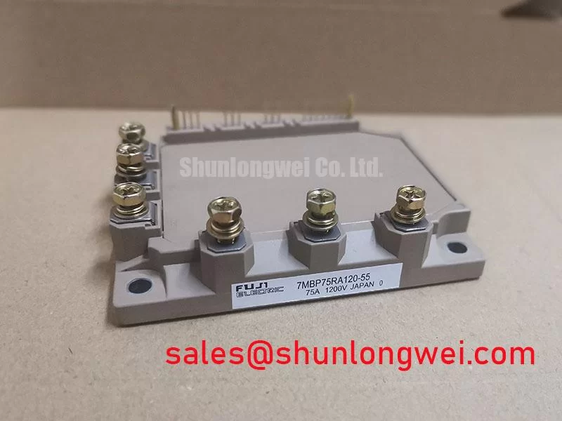
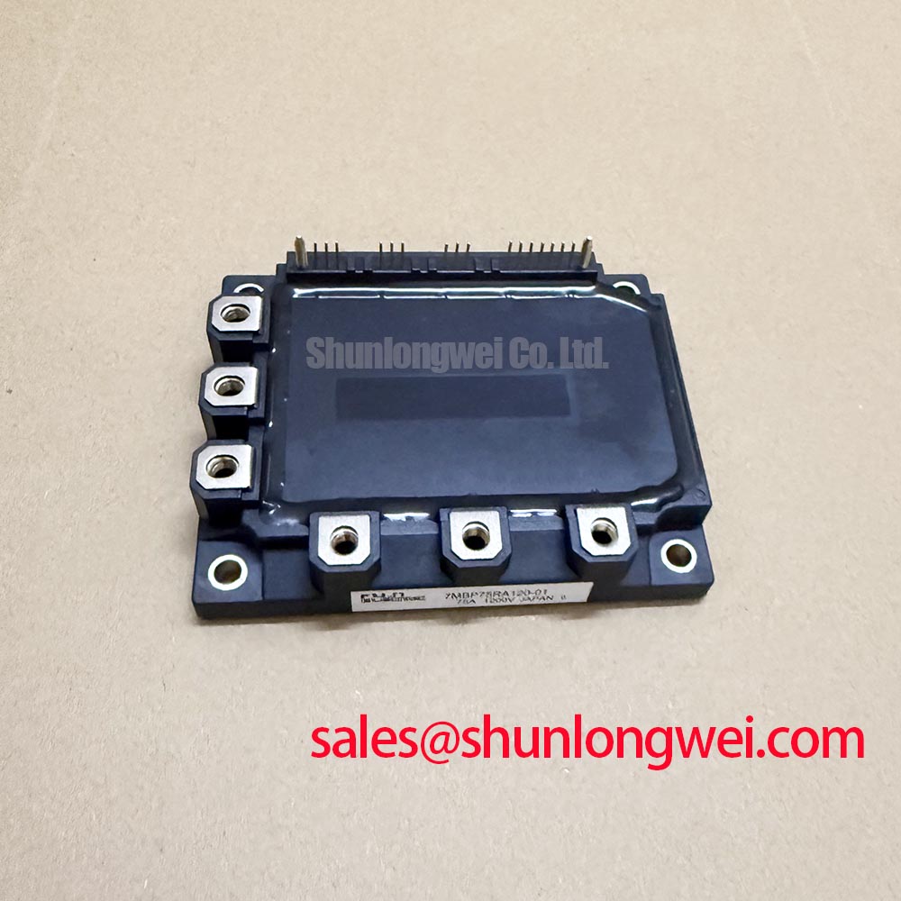
7MBP75RA120-01 Specifications and Compatibility Assessment
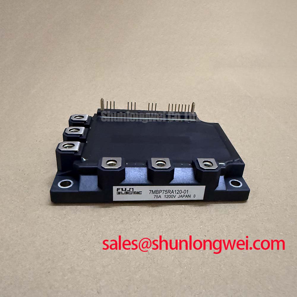
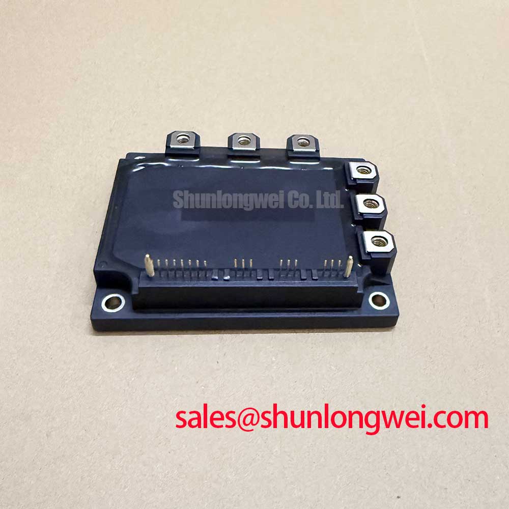
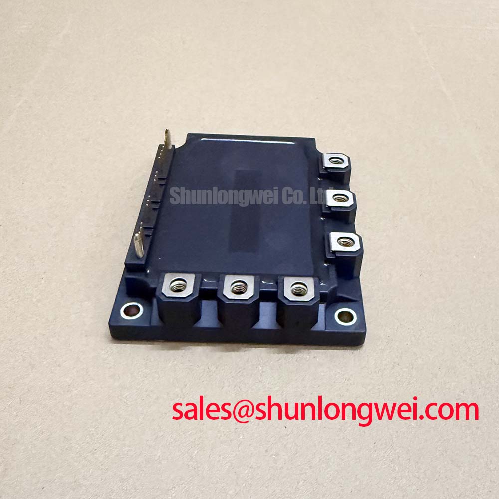
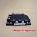
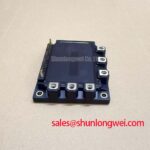
Begin by confirming the inverter nameplate and isolating the DC link, then compare the installed power stage against the 7MBP75RA120-01 electrical limits before applying any test voltage. This Fuji Electric power module is officially rated at 1200 V collector-emitter voltage and 75 A continuous collector current at a case temperature of 80 C. Its maximum specified junction temperature is +150 C, with 360 W power dissipation per IGBT and 2500 V AC isolation for one minute. These ratings establish the component boundary; they do not replace measurement of the actual DC bus, cooling path, switching waveform, or gate-drive behavior in the host equipment.
| Official Specification | Value |
|---|---|
| Manufacturer | Fuji Electric |
| Collector-Emitter Voltage, VCES | 1200 V |
| Continuous Collector Current, IC at TC 80 C | 75 A |
| Power Dissipation per IGBT, PC | 360 W |
| Maximum Specified Junction Temperature, Tj | +150 C |
| Isolation Voltage, Visol | 2500 V AC for 1 minute |
For industrial electric material-handling equipment, these figures support a disciplined compatibility assessment of a traction inverter power stage. Forklift and warehouse-drive systems experience repeated acceleration, regenerative events, changing battery voltage, and temperature cycling. The published voltage, current, thermal, and isolation ratings should therefore be compared with the original inverter schematic, cooling arrangement, control board, busbar geometry, and application waveform records. A matching voltage and current rating alone does not establish equivalent switching behavior or mechanical fit.
7MBP75RA120-01 Thermal-Electrical Optimization: Junction-to-Case Thermal Network Simulation and Practical Tuning
During a repair assessment, inspect the module mounting surface and heatsink plane before treating a high-temperature event as a semiconductor failure. Uneven contact pressure, hardened thermal interface material, debris on the baseplate, or a warped heatsink can all increase the thermal path from the IGBT junction to the cooling system. The +150 C maximum specified junction temperature is an Official Specification, while the junction temperature reached during a pulse is system-dependent and must be established from the inverter loss profile and the applicable transient thermal data.
A multi-RC junction-to-case thermal model is useful when the traction drive sees short current peaks instead of steady loading. Each RC branch represents a different heat-storage and heat-transfer time constant, so a brief overload cannot be evaluated correctly by relying only on a steady-state thermal resistance assumption. The engineering calculation should combine conduction and switching losses over the actual pulse duration with the relevant transient thermal impedance curve, then add the measured or calculated case-temperature rise. The resulting estimated peak junction temperature must remain within the official +150 C limit under the defined operating conditions.
Design Consideration: thermal measurements should be correlated with the real duty cycle rather than a generic current label. A forklift traction inverter may spend limited time at a high torque command while repeatedly cycling through lower torque, deceleration, and standstill states. Cooling airflow, heatsink contamination, enclosure temperature, battery regeneration, and switching frequency can shift the loss balance. Engineers should record case temperature, DC-link voltage, phase current, and operating state together so that a temperature rise can be associated with a measurable condition rather than a presumed cause.
When reinstalling a module, use a clean and flat contact plane, distribute the thermal interface material as a thin continuous film, and tighten mounting hardware in the sequence and torque specified by the original equipment documentation. The module manufacturer’s mechanical drawing and the equipment service manual remain the authority for mounting-hole configuration and torque requirements. Safety Interlock Note: Disconnect and verify discharge of the DC link before removing gate-drive or power terminals, because stored energy can remain hazardous after normal shutdown.
Repeated battery charge and discharge operation can create wide thermal cycling in the inverter assembly. The practical response is not to claim a lifetime from a temperature reading, but to reduce avoidable temperature excursion through verified cooling contact, stable bus connections, and a switching strategy validated on the complete system. For an alternative module evaluation, the 6MBI100S-140 should be compared against the original circuit, terminal arrangement, thermal interface, drive requirements, and protection implementation before any substitution decision.
Transient Dynamics and Electrical Design: High-Frequency Common-Mode Bearing Current on 7MBP75RA120-01
Measure the motor-terminal waveform at the inverter output when investigating unexplained drive trips, bearing-current concerns, cable insulation stress, or inconsistent motor behavior. Long motor cables can act as transmission lines. A mismatch between cable impedance and motor termination can reflect a switching edge back toward the inverter and raise terminal voltage above the expected DC-link-related value. The magnitude depends on cable construction, cable length, motor impedance, switching transition, output filter placement, and the physical layout of the inverter.
The 1200 V VCES rating is the official collector-emitter blocking limit, not a permission to infer acceptable overshoot from a nominal DC bus alone. Design Consideration: minimize commutation-loop inductance to suppress turn-off inductive overshoots, then verify peak voltage margin against the DC-link voltage by switching tests with a suitably rated measurement method. A compact, symmetric busbar arrangement can reduce imbalance between commutation paths. Gate-loop routing should remain short and controlled because parasitic inductance can alter gate-emitter voltage during high current transitions.
Common-mode voltage transitions can couple through motor capacitance, cable shield paths, encoder wiring, and chassis connections. Bearing-current mitigation is a system issue involving motor construction, cable routing, grounding architecture, output filtering, and switching behavior. Engineers should inspect oscilloscope waveforms against a known-good signal path and check whether the condition changes with cable routing, motor connection, filter installation, or inverter operating mode. This approach avoids assigning a single cause to a waveform that may arise from several coupled mechanisms.
Switching-frequency selection also requires a thermal assessment. Between low and higher PWM frequencies, conduction and switching losses redistribute, while acoustic behavior, motor current ripple, output-filter requirements, and electromagnetic behavior may change. The official 360 W per IGBT dissipation rating defines a published component limit, but it does not provide a complete switching-loss result for a particular inverter. Designers should calculate and test the complete loss budget at the intended current, voltage, cooling condition, and modulation pattern.
In a broader converter assembly, rectification and inverter sections should be evaluated as interacting power stages rather than independent catalog entries. Where a front-end or complementary power-stage review is needed, the 6MBI450U-120A-05 can be assessed against the system topology, bus voltage, cooling configuration, and protection architecture. For device-level switching principles and application context, consult the Fuji Electric V-Series IGBT Application Manual.
7MBP75RA120-01 Operational Boundaries: Evaluating Desaturation Detection Limits
Desaturation protection should be tested as part of the installed gate-drive system, because the protection response depends on sensing components, blanking behavior, driver output capability, cable layout, power-loop inductance, and the switching state at fault onset. The module’s official ratings identify the voltage, current, thermal, and isolation boundaries available here; they do not establish a universal short-circuit withstand interval or a universal desaturation threshold. Those values must come from the applicable gate-driver documentation and verified equipment design.
During commissioning, technicians can examine the collector-emitter waveform, gate-emitter waveform, current response, and fault-latch behavior using properly isolated instrumentation. A desaturation event may be associated with a shorted motor phase, a gate-drive supply problem, an abnormal load, a connector issue, or an actual power-stage fault. Comparing the affected phase with an equivalent known-good phase under controlled conditions is more defensible than interpreting one static resistance check as a complete diagnosis.
Engineering Recommendation: use a controlled turn-off strategy that limits the risk of excessive inductive overvoltage when a protection event interrupts current. The needed behavior depends on stray inductance, current, DC-link voltage, clamp network, and driver characteristics. Engineers should confirm the response with double-pulse or equivalent controlled switching tests before putting the traction inverter back into duty. A metal-oxide varistor or other transient suppression network, where present in the original assembly, must be evaluated as part of the coordinated protection system rather than treated as an independent cure for all overvoltage events.
Gate-drive immunity matters particularly during rapid collector voltage movement. Miller coupling can raise the effective gate voltage of a device intended to remain off, especially when return paths share inductance with power current. Design Consideration: keep the gate return path controlled and separate it from high-current commutation paths where the original design permits, then verify off-state gate behavior during the worst expected switching transitions. The Evolution of Negative Off-Bias Gate Drive Circuits provides technical context for evaluating off-state gate-drive approaches; the required drive levels and component values must be confirmed from the original module and driver documentation.
Field Diagnostics and Commissioning: Isolated DC-DC Power Supply Sizing for High-Current 7MBP75RA120-01 Topologies
Before energizing a repaired inverter, confirm that every isolated gate-drive supply reaches its required voltage under control-board load and remains stable through enable, PWM activity, and fault shutdown. A supply that appears correct with no switching can behave differently when gate charge is repeatedly drawn, when a protection circuit activates, or when common-mode voltage transitions couple into the isolation barrier. The original gate-driver design documentation should define the required supply rails, isolation class, start-up order, and fault-state behavior.
The module’s 2500 V AC isolation voltage for one minute is an Official Specification for the module isolation test condition. It must not be represented as a complete system insulation certification, reinforced isolation rating, or common-mode transient immunity rating for the finished inverter. Those system properties depend on the gate driver, isolated DC-DC converter, printed-circuit-board creepage and clearance, wiring, enclosure, contamination level, and applicable end-equipment standards.
A practical commissioning sequence begins with an unpowered visual inspection of terminal hardware, heatsink contact, gate-drive connectors, current-sensing paths, and motor leads. With controlled power applied, verify supply rails and interlocks before enabling PWM. Capture each phase gate waveform and collector-emitter waveform under a limited, representative operating condition, then progress only after confirming that the protection system responds predictably. Any unexpected gate pulse, unstable supply rail, or repeated fault should be investigated before returning the electric material-handling drive to service.
Fuji Electric’s power semiconductor product information is a useful manufacturer reference when reviewing device-family context. For the installed 7MBP75RA120-01, final acceptance should remain tied to the original equipment schematic, applicable Fuji Electric documentation, controlled measurements, and the actual inverter operating envelope.