

Content last revised on October 28, 2026
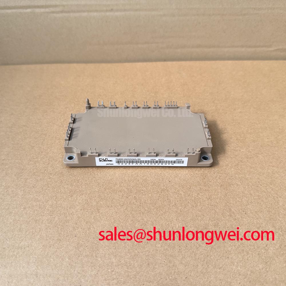
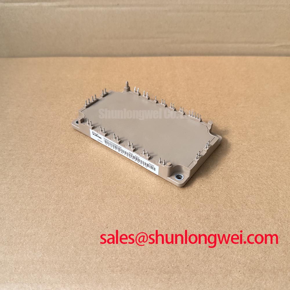
Preventing Spurious Faults: Type-2 Coordination for Protecting IGBT Modules in 7MBR100SD060-50
Compare the semiconductor fuse’s total clearing behavior with the fault exposure of the complete power circuit, rather than selecting a fuse from its current rating alone. Design Consideration: total clearing I²t, prospective fault current, DC interruption capability, and circuit inductance influence the energy delivered before isolation. A fuse can limit a sustained fault without necessarily acting quickly enough to protect an IGBT during its initial short-circuit interval.
Separate the protection tasks on the schematic. Electronic fault detection and controlled gate shutdown address semiconductor switching faults; the fuse and upstream disconnect address interruption and isolation under their specified conditions. Type-2 coordination is an equipment-level assessment, not an inherent property of the 7MBR100SD060-50. Neither a semiconductor fuse designation nor an I²t comparison alone establishes that a module enclosure will remain intact during every DC-link fault.
When investigating unexplained fuse operation, preserve the distinction between an overload event and a rapid semiconductor fault. Review the trip record, current-sensor output, precharge sequence, and gate-driver fault status where these records exist. Check fuse-holder contact condition and busbar fastening because local heating can affect the protection assembly independently of module switching behavior. Do not increase the fuse rating simply because the previous fuse opened during startup.
Inspect conductor spacing around the power terminals after installation, including the actual position of cable lugs, washers, barriers, and adjacent grounded metal. Design Consideration: clearance and creepage requirements depend on working voltage, transient exposure, pollution conditions, insulation materials, and the applicable equipment standard. Conductive debris, displaced hardware, or a busbar edge can compromise the intended arrangement even when the module itself fits the mounting footprint.
Trace any regenerative-energy path separately from the fault-interruption path. Where the host converter uses a braking chopper and resistor, assess the resistor’s energy capacity, switching control, and overtemperature protection against the equipment duty. Do not infer the braking connections or permissible resistor loading from the PIM designation. The circuit drawing must identify which terminals participate in rectification, inversion, and braking before continuity measurements are interpreted.
For manufacturer technical resources and semiconductor support channels, consult Fuji Electric Europe Semiconductor & Power Electronics. Protection qualification should remain tied to the exact module documentation and the equipment’s tested protection arrangement, rather than specifications borrowed from another Fuji product family.
7MBR100SD060-50 Circuit Protection & Reliability: Preventing Spurious Power-Up Shoot-Through
Capture the auxiliary supply, driver-ready signals, gate-emitter waveforms, and DC-link rise on the same startup timeline when investigating power-up shoot-through. Engineering Recommendation: the control system should hold switching commands inactive until the driver supplies and undervoltage interlocks are stable. Shutdown sequencing also matters: removing driver power while the DC link remains energized can leave the switching stage outside its intended controlled state.
A negative gate bias is not a universal prescription for this module. Select the off-state drive arrangement from the device limits and driver architecture, then assess its behavior during startup, shutdown, and rapid commutation. Miller-coupled gate disturbance depends on switching conditions and the impedance of the complete gate-return path. Measure at the relevant device terminals with an appropriate probing arrangement rather than treating a controller-side logic trace as proof of a secure off state.
For replacement assessment, compare interfaces before comparing purchasing descriptions. The 7MBP75TEA060 is a separate Fuji model to investigate, not an established direct replacement for the 7MBR100SD060-50. Its different designation does not establish interchangeable drive requirements, terminal functions, current capability, or mechanical fit.
| Selection checkpoint | 7MBR100SD060-50 | 7MBP75TEA060 comparison requirement |
|---|---|---|
| Manufacturer | Fuji Electric | Fuji Electric |
| Rated voltage | 600 V — Official Specification | Consult exact-model datasheet |
| Rated current | 100 A — Official Specification | Consult exact-model datasheet |
| Package | Fuji Power Module | Compare outline, mounting, and terminal drawing |
| Control compatibility | Evaluate with the existing driver schematic | Compare drive interface and protection implementation |
| Replacement status | Reference model | Not established as a drop-in replacement |
When assessing compatibility for a commercial string inverter or micro-grid energy-storage converter, map the actual power topology before assigning module roles. A separate device such as the 7MBR75VZ120-50 requires its own circuit and rating review; it should not be assigned as a front-end or auxiliary-stage component merely because its part number belongs to a related product range. Battery charge and discharge operation also require evaluation of current direction and the resulting thermal loading.
During startup testing, diode commutation can generate ringing that couples into gate or fault-signal wiring. Distinguish a genuine protection event from measurement pickup by checking probe routing and correlating the signal with power-terminal waveforms. Snubber changes should follow that diagnosis, not substitute for it. Pro Tip: Keep outgoing and return commutation conductors closely coupled, then verify turn-off voltage margin with a suitably controlled double-pulse test before accepting the layout.
7MBR100SD060-50 Operational Boundaries: Mitigating Commutation Turn-Off Voltage Spikes
Measure collector-emitter overshoot and diode recovery behavior at representative load and temperature conditions before accepting a revised busbar or driver arrangement. Design Consideration: recovery current interacts with circuit inductance and the opposing switch’s turn-on behavior, so ringing cannot be attributed to the diode alone. Evaluate waveform shape, peak stress, and repeatability together rather than judging the circuit from a single oscilloscope capture.
Tailoring turn-on gate resistance can change commutation speed, recovery stress, and switching loss. An RC snubber can damp a particular oscillatory path, but its placement, dissipation, and pulse capability must suit that path. Select these measures from measured behavior and the system thermal budget; neither a universal resistor value nor an assumed recovery-current limit is justified for the 7MBR100SD060-50.
Use the Fuji Electric IGBT module resources, including X-Series information to distinguish product generations and locate relevant manufacturer material. Characteristics belonging to newer module families must not be transferred to this model. The separate article The 1200 V CoolSiC™ MOSFET Advantage in Three-Phase Power Conversion provides technology background, not Fuji-authorized specifications or replacement qualification for this silicon IGBT module.
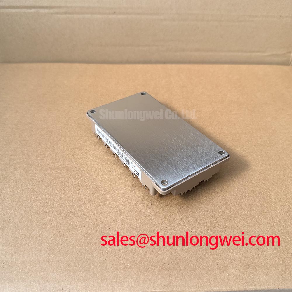
Restore the thermal interface before evaluating sustained operation. Clean the mating surfaces, inspect heatsink flatness, and apply the specified interface material using the approved assembly method. Mounting torque and interface thickness must follow the applicable mechanical instructions; excessive material or uneven clamping can impair heat transfer. Keep terminal tightening separate from baseplate fastening so cable forces do not disturb the mounting arrangement.
For equipment with repeated charge and discharge cycles, assess case-temperature excursions alongside current and cooling conditions. Engineering Recommendation: reducing avoidable temperature swings through suitable cooling control and operating strategy can reduce thermal cycling stress, but no service-life extension should be assigned without a supported mission-profile analysis. After reassembly, compare temperature distribution and switching waveforms under controlled loading, and investigate persistent local heating before returning the converter to unrestricted duty.