Content last revised on September 24, 2026
Field Diagnostics & Commissioning: Cosmic Ray Robustness: Voltage Derating Considerations in 7MBR75XPE120-50 Topologies
Cosmic-ray and terrestrial-neutron effects are system reliability topics rather than confirmed performance specifications for this individual module. A repair engineer working above approximately 2000 m altitude may wish to review the site environment because atmospheric particle exposure can vary with altitude, shielding, operating voltage, and semiconductor construction. No specific single-event burnout FIT rate should be assigned to the 7MBR75XPE120-50 without a manufacturer qualification report or an applicable reliability study.
The useful field action is to establish the real electrical stress at the module terminals. Record the maximum DC-link voltage during regeneration, startup, plugging, and fault recovery, then compare the measured switching overshoot with the module’s official voltage rating of 1200.0 V. A high-voltage differential probe and a suitably rated measurement setup should be used by qualified personnel. The system designer should determine the required voltage derating after considering bus tolerance, transient amplitude, modulation behavior, braking energy, and measurement uncertainty.
Layout inspection is equally important. Keep the commutation loop compact, avoid unnecessary conductor area, and use a symmetrical laminated bus or equivalent low-inductance arrangement where the equipment permits it. Clearance and creepage must be assessed against the working voltage, pollution level, enclosure conditions, and the relevant equipment standard. These are design considerations, not factory-certified dimensional values for this module.
During troubleshooting, compare a failed unit with a known-good signal path. Check gate-emitter impedance only after the equipment is fully discharged and the gate-driver connection has been isolated as required by the equipment design, inspect the DC-link precharge sequence, and verify that the gate driver does not command switching while the power stage is in an undefined state. If a module fails after a high-energy switching event, do not attribute the event to cosmic radiation alone; investigate overvoltage, gate disturbance, cooling loss, short-circuit stress, and mechanical connection quality as competing possibilities.
For the wider semiconductor context, engineers can consult Fuji Electric Power Semiconductor & IPM Modules and the Fuji Electric Power Semiconductors Portal. A technically similar catalog reference such as 6MBI100S-140 should be treated only as a separate comparison point; terminal arrangement, ratings, gate requirements, and mechanical compatibility still require independent confirmation.
7MBR75XPE120-50 Operational Boundaries: Evaluating Optocoupler and Digital Coreless Transformer Limits
The supplied product data identifies the device as a 1200.0 V, 75.0 A Fuji Electric module, but it does not establish a reinforced isolation rating above 5 kV or a common-mode transient immunity value above 100 kV/µs. Those figures must not be treated as properties of the module without the relevant driver and isolation documentation. The isolation barrier normally belongs to the gate-driver architecture, not to the power module rating alone.
When replacing a module in a forklift traction inverter, map every driver output to the original control topology before energizing the DC link. An optocoupler-based driver and a coreless-transformer driver can respond differently to common-mode movement, propagation delay, supply undervoltage, and reset behavior. The integrator should verify isolation voltage, working voltage, CMTI, pulse-width distortion, fault feedback, and gate-emitter protection using the selected driver’s own datasheet.
Spurious turn-on risk should be assessed at the gate pins while the complementary device is switching. Probe the gate and emitter reference with a measurement method that preserves the actual common-mode relationship. If the observed waveform contains ringing or a false pulse, review driver return routing, power loop coupling, Miller current, clamp behavior, and the placement of local bypass components. The correct damping value is system-dependent and should be established through controlled bench testing rather than copied from an unrelated module.
Freewheeling diode behavior also affects the switching cell. Reverse-recovery current can interact with stray inductance and create voltage overshoot, additional electromagnetic emission, and higher stress on the switching transistor. A snubber or output network may reduce the observed disturbance, but its topology and values must be selected from measured waveforms, switching conditions, motor characteristics, and thermal results. The product page does not confirm a particular diode recovery profile or snubber requirement for this model.
Safety Interlock Note: Disconnect and verify the DC link is discharged before removing gate-driver connectors or touching the module terminals.
For a structured review of gate-loop behavior, use the engineering reference Precision Gate Drive Design. It should support, not replace, the driver manufacturer’s isolation data and the equipment designer’s oscilloscope validation.
7MBR75XPE120-50 Thermal-Electrical Optimization: Static and Dynamic Current Distribution for Practical Tuning
The official current classification supplied for this product is 75.0 A. That figure should not be interpreted as a universal continuous current under every forklift traction duty cycle. Actual allowable current depends on case temperature, cooling method, switching loss, conduction loss, modulation pattern, overload duration, and the manufacturer’s specified test conditions. Before selecting the module for a repair, match the original heatsink, thermal interface, airflow or liquid cooling arrangement, and protection strategy.
When modules or semiconductor paths are operated in parallel, the positive temperature coefficient commonly associated with on-state voltage can support static current sharing as device temperature rises. This is a design consideration rather than a guaranteed sharing result for every circuit. Differences in junction temperature, wiring resistance, gate threshold, driver timing, and thermal contact can still create unequal current distribution.
Dynamic sharing is more sensitive to layout. Gate wiring should be matched in length and impedance where parallel switching paths are used, and the power conductors should present comparable commutation paths. Avoid routing one gate return beside a high-current switching conductor while placing the other return in a quieter region. The objective is to reduce timing and inductive imbalance; the final result should be verified with simultaneous voltage and current measurements.
Thermal commissioning should begin with temperature sensors positioned to identify the hottest credible mounting area, followed by controlled load steps that reflect the real traction profile. Observe case temperature, gate waveform, DC-link ripple, phase current, and fault behavior together. A stable static temperature does not prove safe dynamic operation, because switching loss may rise during acceleration, regenerative braking, or motor current reversal.
Surge current and short-duration overload capability require special care. The supplied parameter set does not include an ITSM value, a repetitive overload curve, a transient thermal impedance curve, or a junction-temperature recovery window. Do not infer these limits from the 75 A rating. Engineers should retrieve the applicable Fuji Electric data and compare the real pulse duration, starting temperature, repetition rate, and fault-clearing time with the published test conditions.
After installation, inspect the thermal interface for uniform contact and confirm that mounting pressure follows the equipment or manufacturer instructions. A module that operates acceptably at low load may still show excessive temperature rise when the motor reaches peak torque or when regenerative energy returns to the DC link. Field diagnosis should therefore compare thermal and electrical measurements under the same operating sequence rather than relying on a single idle or low-load check.
Assembly Integrity & Layout Architecture: Implementing a Sinusoidal Output Filter or dv/dt Reactor
Long motor leads can behave as a transmission-line system. Reflections caused by cable impedance, motor input impedance, termination behavior, and switching edge rate may increase the voltage seen at the motor terminals. The often-cited possibility of a terminal peak approaching twice the applied step voltage is a system-level transmission-line condition, not a confirmed stress figure for the 7MBR75XPE120-50. Cable length, geometry, installation routing, motor design, and inverter switching behavior determine the actual waveform.
Measure the phase-to-phase and phase-to-ground voltage at the inverter and motor ends when evaluating a forklift traction installation with extended cable routing. Use probes and bandwidth limits suitable for the switching environment, and ensure that the measurement connection does not create a misleading ground loop. Compare the measured peak, rise time, repetition rate, and ringing with the module’s official voltage boundary and the motor insulation requirements.
A dv/dt reactor can slow the voltage transition and reduce cable-related stress while retaining more of the inverter’s fundamental waveform. A sinusoidal filter can provide stronger waveform reconstruction, but it introduces additional impedance, losses, resonance considerations, and possible effects on current control. Selection should therefore be based on the motor cable, carrier frequency, motor insulation, required torque response, filter thermal behavior, and the inverter control algorithm.
Do not size an output reactor from the module’s 1200 V rating alone. The system engineer should define the acceptable motor-terminal waveform, assess the filter’s interaction with the DC link and current loop, and validate the result during acceleration, steady traction, regenerative braking, and fault recovery. The final layout should keep the high-current paths short, separate sensitive gate and feedback wiring from output conductors, and provide a clearly controlled protective-earth arrangement.
Commissioning should include a visual inspection of busbar joints, terminal fasteners, insulation barriers, cable screens, and filter connections. A loose connection can add localized heating and electrical noise without immediately producing a clear drive fault. If the replacement module shows abnormal switching noise, compare the inverter-side and motor-side waveforms before changing gate resistance or protection thresholds. This prevents a filter, cable, grounding, or measurement problem from being mistaken for an intrinsic module defect.
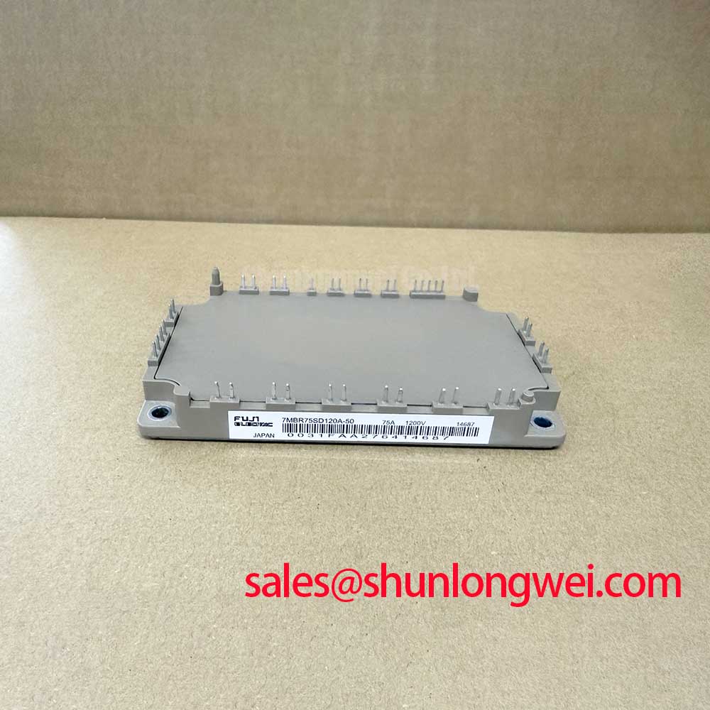
For procurement and replacement evaluation, retain the documented identity Fuji Electric 7MBR75XPE120-50, its confirmed 1200.0 V voltage rating, 75.0 A current rating, and Module package classification. Mechanical fit, terminal assignment, gate-drive compatibility, cooling performance, surge capability, and complete protection coordination remain conditions for system approval and must be verified against the original equipment documentation.