

Content last revised on September 22, 2026
Field Diagnostics and Commissioning for A76L-0300-0189 Topologies
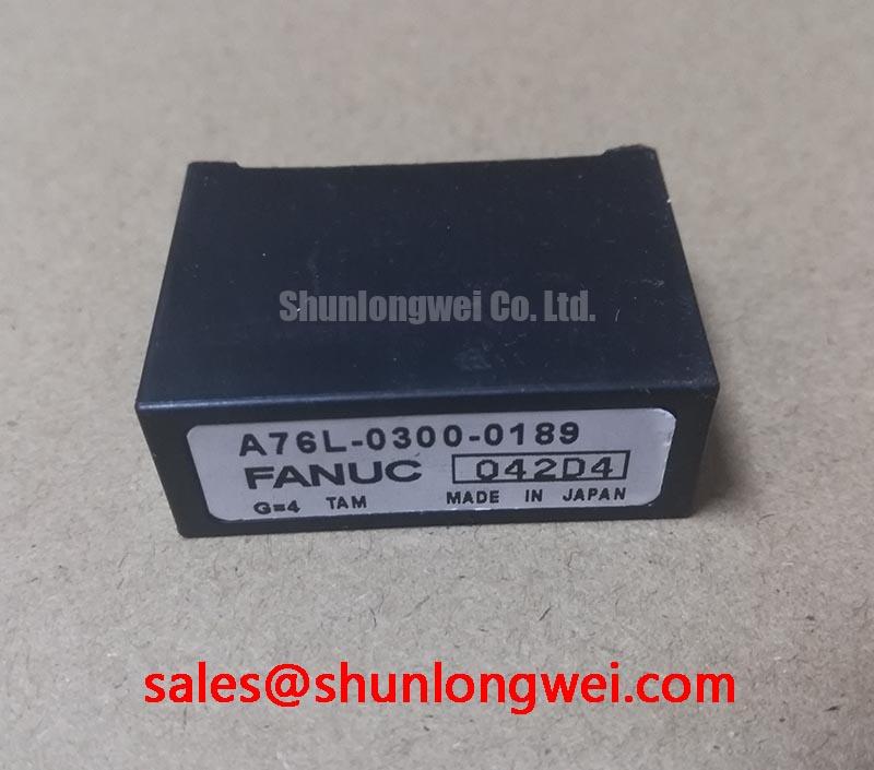
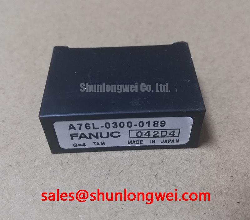
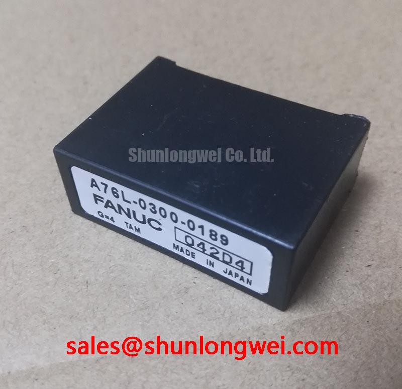
Verify the nameplate ratings, inspect the power terminals for contamination, and record cold-state resistance readings before connecting A76L-0300-0189 to any energized assembly. The available product data identifies this FANUC CNC Servo Power Module as an IGBT Module with an official rated voltage of 600.0 V and rated current of 50.0 A. These values define the component-level electrical boundary; the installed inverter or servo drive still requires system-level verification of switching conditions, cooling, protection, and control compatibility.
| Manufacturer | FANUC |
| Model | A76L-0300-0189 |
| Product category | IGBT Module |
| Package or housing description | CNC Servo Power Module |
| Rated voltage | 600.0 V, Official Specification |
| Rated current | 50.0 A, Official Specification |
When assessing this module in a commercial string inverter or micro-grid energy-storage power stage, begin with isolation, visual inspection, and a comparison against the original equipment documentation. The official 600.0 V rating should not be treated as permission to operate at the same DC-link voltage without checking switching overshoot, transient conditions, ambient temperature, cooling performance, and the protection limits of the complete drive. A module rating and a converter operating envelope are different engineering references.
Altitude, enclosure ventilation, and contamination can change the electrical and thermal stress seen by a power module. Terrestrial neutron effects and single-event burnout are reliability topics that require application-specific device data, operating-voltage data, altitude assumptions, and a recognized reliability model. No FIT or SEB rate should be assigned to A76L-0300-0189 without an authoritative source covering this exact device and operating condition. As a Design Consideration, engineers evaluating installations above 2000 m should review the original equipment maker’s altitude guidance, creepage and clearance requirements, cooling derating, and DC-bus transient records rather than applying an assumed failure multiplier.
During commissioning, use a controlled low-energy test arrangement where possible. Confirm that the gate-control board, current feedback, fault latch, and DC-link precharge sequence behave as expected before applying full operating voltage. Affected phase legs should be compared with a known-good channel using appropriately rated differential voltage probes and current sensors. A Rogowski coil can be useful for observing fast transient current behavior; its operating principle is described by Rogowski Coil Principle for Fast Transient Current Sensing. For lower-bandwidth monitoring and feedback design, engineers may also review ADI High Precision Current Sense Amplifiers.
Clearance and creepage must be assessed from the actual assembly, pollution environment, insulation system, and applicable product standard. Avoid inferring a safe spacing value from the module’s voltage rating alone. Inspect busbar alignment, terminal flatness, washer condition, and signs of localized heating. Maintenance Note: isolate and discharge the DC link before disconnecting control or power wiring, then periodically check heatsink airflow and terminal temperature under comparable load.
A76L-0300-0189 Thermal and Electrical Optimization
The rated current of 50.0 A is an Official Specification, but usable current in service depends on switching frequency, case or heatsink temperature, duty cycle, airflow, overload duration, and the complete thermal path. Before returning a repaired inverter to production, inspect the heatsink contact surface, remove degraded thermal-interface material, and verify that the cooling fan, ducting, and temperature sensors operate correctly. A clean heatsink cannot compensate for poor mechanical contact or uneven pressure.
IGBT conduction behavior changes with temperature and current. In parallel power paths, a positive temperature coefficient of conduction voltage can support static current sharing under suitable conditions, but it does not automatically guarantee balanced dynamic switching. Gate-loop geometry, common-emitter inductance, driver propagation delay, and busbar symmetry must be checked together. This is a Design Consideration, not an A76L-0300-0189 manufacturer guarantee. During waveform testing, compare gate-to-emitter voltage, collector-emitter voltage, and phase current at the same time base to identify unequal turn-on or turn-off behavior.
Short-circuit protection requires more than a nominal desaturation threshold. The driver must detect abnormal collector-emitter behavior, establish a controlled soft turn-off response, and coordinate the fault latch with the system controller. The requested sub-three-microsecond detection figure is not included in the supplied official product data, so it should not be represented as a specification of this module. Designers should verify the actual protection timing from the gate-driver documentation and confirm that the module remains within its published short-circuit safe operating area, if such data is available for the exact device.
For high-duty inverter service, review the complete thermal-electrical path rather than relying on a single temperature reading. Measure temperature near the module mounting interface, compare phase-leg heating, and inspect for rising contact resistance at power terminals. The SKM100GB063D may be reviewed as a separate same-class reference during a design study, but electrical, mechanical, gate-drive, and protection compatibility must be established independently before considering any interchange.
A76L-0300-0189 Operational Boundaries for Isolated Gate Control
The supplied data identifies the package as a FANUC CNC Servo Power Module, but it does not specify the internal gate-driver architecture, isolation rating, common-mode transient immunity, pin assignment, supply voltage, or timing limits. The system integrator should verify these details from the original FANUC equipment documentation and the applicable drive schematic. Do not infer a reinforced isolation barrier greater than 5 kV or a CMTI capability greater than 100 kV per microsecond from the 600.0 V module rating.
Optocoupler and digital-isolator choices affect propagation delay, pulse-width distortion, reset behavior, and common-mode transient performance. During troubleshooting, probe the driver-side signal and the module-side gate signal separately, using isolated measurement equipment and a controlled switching condition. A missing pulse, unexpected pulse width, or irregular fault response may indicate a driver supply problem, isolation-channel disturbance, grounding issue, or gate-loop impedance mismatch; verify each possibility against a known-good signal path rather than assigning a single cause.
High-frequency switching currents should remain confined to the intended power and gate-return loops. As a Design Consideration, minimize parasitic loop inductance and separate high-current commutation paths from sensitive feedback and communication wiring. The required spacing, shielding, and filter arrangement are determined by the enclosure, insulation system, switching waveform, and applicable safety or EMC evaluation. The module itself should not be described as independently compliant with complete-equipment EMC standards.
In a micro-grid storage converter, precharge behavior and control-power sequencing deserve particular attention. Confirm that the DC link reaches its intended state before gate pulses are enabled, and verify that undervoltage lockout and fault reset behavior do not produce an unintended partial pulse. Any auxiliary supply voltage must be confirmed from the original panel or drive documentation; it should not be guessed from the module model number.
Benchtop Waveform Tuning and Dynamic Gate Impedance Control
Begin bench tuning with the lowest practical switching energy and a current-limited DC source. Record the gate waveform at the module terminals rather than only at the driver output, because connector resistance, return-path inductance, and wiring can alter the voltage seen by the semiconductor. Check turn-on delay, turn-off behavior, ringing, Miller-region disturbance, and the relationship between gate voltage and collector-emitter transition.
Active Miller clamp circuits, negative gate bias, and low-impedance gate paths are application-level design options, not confirmed features of A76L-0300-0189. The supplied product information does not specify a negative gate-bias requirement or a permitted negative gate voltage, so values such as minus five to minus fifteen volts must not be presented as a prescription for this module. When a designer evaluates these methods, the gate-emitter absolute maximum rating, driver capability, isolation behavior, and turn-off transient must be verified from the relevant technical documentation.
Cross-conduction risk should be examined through measured dead time, driver propagation mismatch, Miller-induced gate movement, and the actual commutation loop. If a phase leg shows excessive overshoot or unexpected current overlap, review busbar inductance, gate-return routing, driver supply decoupling, clamp behavior, and probe technique. The correct gate resistance is system-determined; it should be tuned from measured switching loss and voltage overshoot while keeping the device within its documented electrical and thermal boundaries.
For a phase-controlled rectifier or front end connected to an industrial AC network, conduction angle and current-shaping strategy influence harmonic content. The module’s voltage and current ratings do not by themselves establish compliance with grid-current or power-quality requirements. Engineers should evaluate line impedance, filter design, control timing, and the applicable installation standard using measured line current. Fast semiconductor fuses may also be coordinated with the power stage, but the fuse I²t, prospective fault current, bus capacitance, and module short-circuit withstand must be evaluated as one protection system.
For broader principles covering power-device selection, switching stress, thermal verification, and reliability assessment, consult the Power Electronics Masterclass as a technical reference. Final commissioning should be based on measured waveforms, verified protection timing, thermal checks, and the original FANUC equipment requirements.