Content last revised on June 26, 2026
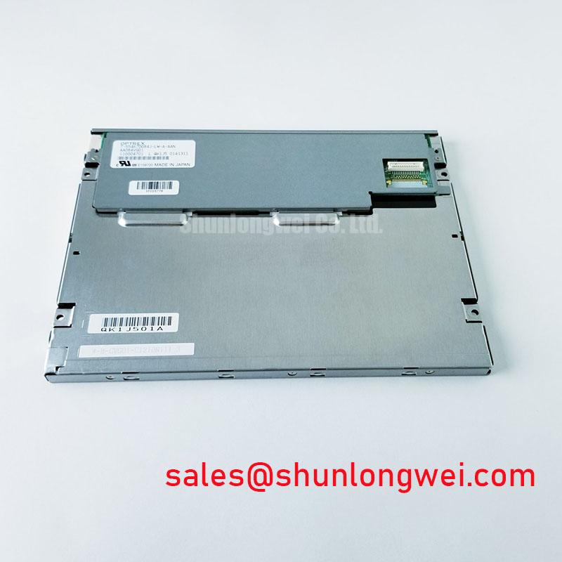
Mitsubishi AA084SB01: 8.4-inch SVGA Display Engineered for Industrial Reliability
Application Scenarios & Value
Delivering Robust Visual Performance in Demanding Operational Environments
The Mitsubishi AA084SB01 is an 8.4-inch a-Si TFT-LCD module engineered for longevity and clarity in applications where operational readiness is non-negotiable. Its primary value lies in its wide operating temperature range and high-reliability backlight system, making it a steadfast choice for industrial control panels, human-machine interfaces (HMIs), and specialized test and measurement equipment. For systems requiring consistent performance across fluctuating thermal conditions, from factory floors to outdoor-adjacent enclosures, the AA084SB01 delivers stable visuals. Its SVGA (800 x 600) resolution provides the necessary detail for complex graphical interfaces without demanding excessive processing power. This makes it an ideal fit for upgrading legacy systems or deploying new mid-range diagnostic tools where visual precision and environmental resilience are paramount.
What is the primary benefit of its long-life backlight? It provides an estimated 100,000 hours of operational life, significantly reducing total cost of ownership. The module's design addresses the common engineering challenge of ensuring HMI readability and durability in environments that are subject to extreme temperatures. While the AA084SB01 is optimized for SVGA resolution, for applications demanding higher pixel density in a similar form factor, the AA084XA02 offers an XGA alternative. For systems where a different aspect ratio or size is required, the AA104VH01 provides a 10.4-inch VGA display solution.
Key Parameter Overview
Functional Specifications for System Integration
The technical specifications of the AA084SB01 are tailored for seamless integration into industrial-grade systems. The combination of a standard LVDS interface, a wide thermal operating envelope, and high optical performance provides a versatile foundation for a variety of human-machine interface designs.
| Optical & Display Characteristics | Value |
| Diagonal Size | 8.4 inches |
| Resolution | 800(RGB)×600, SVGA |
| Brightness | 600 cd/m² (Typ.) |
| Contrast Ratio | 600:1 (Typ.) |
| Viewing Angle (L/R/U/D) | 80°/80°/80°/60° (Typ.) |
| Display Technology | a-Si TFT-LCD, TN, Normally White |
| Electrical & Interface | Value |
| Signal Interface | LVDS (1 ch, 6/8-bit), 20 pins |
| Logic Voltage (VCC) | 3.3V (Typ.) |
| Mechanical & Environmental | Value |
| Outline Dimensions (W x H x D) | 199.5 x 149.0 x 12.0 mm (Max.) |
| Operating Temperature | -30°C to 80°C |
| Storage Temperature | -30°C to 80°C |
| Backlight System | WLED, 100K hours (Typ.), replaceable |
Download the AA084SB01 datasheet for detailed specifications and performance curves.
Technical Deep Dive
A Closer Look at Thermal Resilience and Backlight Longevity
The standout feature of the AA084SB01 is its exceptional operating temperature range of -30°C to 80°C. This wide thermal window is not a common specification and is a critical differentiator for equipment deployed in uncontrolled environments, such as agricultural machinery cabs, non-climate-controlled factory automation cells, or marine bridge instrumentation. This resilience is achieved through careful material selection and component validation, ensuring the liquid crystal maintains its response characteristics and the electronic components operate reliably at temperature extremes. Imagine this range as the display’s operational "all-weather" capability; it's engineered to perform just as reliably on a cold morning startup as it does during peak afternoon heat.
Furthermore, the White LED (WLED) backlight is rated for a 100,000-hour lifetime. This figure, defined as the time until brightness degrades to 50% of its initial value, directly translates to reduced maintenance cycles and a lower total cost of ownership. For a system integrator, this is like choosing an industrial engine rated for 11 years of continuous operation over a commercial one that might last only a fraction of that time. The backlight's design as a replaceable unit further extends the module's serviceable life, a key consideration for long-term industrial deployments where product lifecycle can exceed a decade.
Frequently Asked Questions (FAQ)
Engineering-Focused Inquiries
What is the significance of the -30°C to 80°C operating temperature range for system design?
This extensive range provides engineers with significant design flexibility, enabling the deployment of systems in environments without active heating or cooling. It reduces the need for auxiliary thermal management hardware, simplifying enclosure design, lowering system cost, and improving overall reliability by minimizing potential points of failure associated with fans or heaters.
How does the 600 cd/m² brightness benefit HMI applications?
A brightness of 600 cd/m² ensures strong readability in typical indoor industrial settings with high ambient light. While not designed for direct, full-sunlight exposure, this level of luminance is significantly higher than standard consumer-grade displays, ensuring that operators can clearly read critical data and interact with controls without being hampered by glare from overhead lighting.
Is the LVDS interface on the AA084SB01 compatible with modern single-board computers (SBCs)?
Yes, the single-channel LVDS (Low-Voltage Differential Signaling) interface is a widely adopted standard in the industrial computing space. Most industrial-grade SBCs and controller boards offer native LVDS outputs or compatible expansion options, making the electrical integration of the AA084SB01 a straightforward process for experienced hardware engineers. The 6/8-bit selectable color depth adds another layer of compatibility.
For inquiries regarding the AA084SB01, please contact our technical sales team for further information and to discuss your specific application requirements.