

Content last revised on October 23, 2026
AD400AB160 Circuit Protection & Reliability: Calibrating AC Input Transient Overvoltage Clamping
With the power assembly isolated and stored energy discharged, match the AD400AB160 terminal markings to the equipment schematic before connecting a diode tester. Record forward and reverse readings with the module disconnected from parallel paths; snubbers and surrounding circuitry can otherwise obscure the junction response.
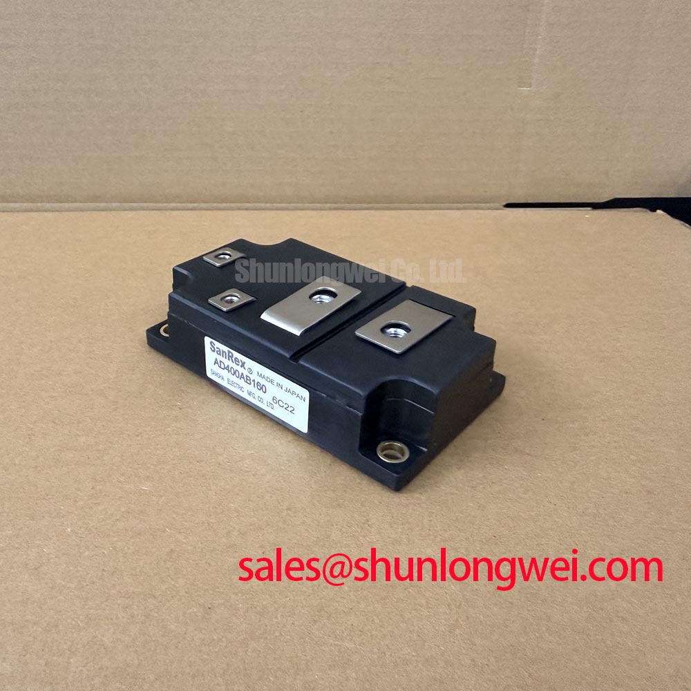
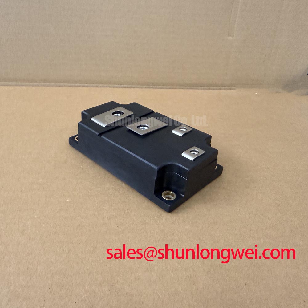
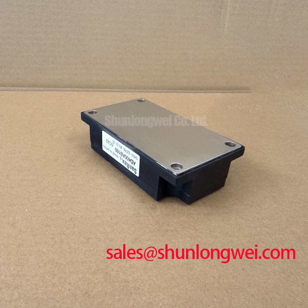
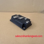
The SanRex AD400AB160 is supplied in a Module package within the thyristor/diode product category. Electrical ratings, internal circuit configuration, terminal assignments, insulation test conditions, and tightening torque: consult the manufacturer datasheet. The SanRex power semiconductor resource provides the manufacturer reference point for matching documentation to the complete part marking.
Compare the installed surge suppressor connections with the AC input schematic before evaluating their clamping performance. Design Consideration: MOV selection depends on continuous line voltage, temporary overvoltage exposure, surge energy, and the voltage actually reaching the semiconductor terminals. A suppressor’s nominal designation alone does not establish adequate protection, especially when connecting leads add inductive overshoot.
The relevant surge immunity reference is IEC 61000-4-5. It describes equipment testing, not an independent surge certification for this module. The equipment engineer should establish the applicable test conditions and measure terminal stress using suitably rated instrumentation. RC suppression addresses a different part of the transient response; its damping action should be assessed together with the source impedance and installed wiring.
For fuse coordination, compare the protective device’s total clearing I²t with the semiconductor’s published surge withstand under compatible waveform, duration, and temperature conditions. Breaking capacity and prospective fault current also belong in that comparison. An ordinary overload rating does not demonstrate semiconductor protection. Record the selected fuse reference alongside the module identification so subsequent maintenance preserves the evaluated combination.
At the mechanical interface, use the specified terminal hardware and tightening procedure rather than a generic module torque. Inspect seating surfaces, cable-lug alignment, and busbar support before tightening. Insulation assessment likewise requires the specified terminal grouping, test duration, and voltage; an improvised withstand test can stress connected circuitry without establishing a meaningful acceptance result.
AD400AB160 Operational Boundaries: Evaluating Blocking-Voltage Transients
Capture the voltage across the relevant blocking junction during the switching events that produce the largest measured disturbance. Design Consideration: off-state dv/dt triggering is a thyristor-specific concern; it must not be assigned to a diode branch simply because both device types appear within the same catalogue category. Interpret each waveform against the documented internal circuit.
An RC snubber should be evaluated for damping, capacitor discharge current, resistor dissipation, and repetitive operating stress. Increasing capacitance is not automatically beneficial: it changes both transient behavior and the current delivered when the associated switching path conducts. Where a series reactor is considered, its saturation behavior and operating losses require system-level assessment rather than an assumed universal inductance value.
During incoming inspection, compare diode-mode readings under consistent temperature and instrument conditions. A low-voltage meter test can reveal an anomalous conduction path, but it cannot establish rated blocking capability, insulation withstand, or dynamic switching performance. General diode behavior is covered by Shindengen’s semiconductor technical resources; model-specific acceptance remains tied to the relevant SanRex documentation.
When assessing a high-voltage three-phase motor solid-state soft starter, engineers should first establish the required phase-leg topology and device function. A comparison with GD300HFX170C6S should therefore begin with circuit configuration, control requirements, and mechanical interfaces, not similar-looking ratings. That reference does not establish interchangeability with AD400AB160.
Assembly Integrity & Layout Architecture: Assessing Firing-Circuit Applicability for AD400AB160
Trace any pulse-transformer secondary to its actual gate and cathode connections before evaluating firing performance. A firing circuit is relevant only where the confirmed assembly contains a controlled thyristor junction; diode junctions have no gate input. Do not infer control terminals from housing shape or transfer another module’s terminal numbering.
Engineering Recommendation: for an applicable thyristor stage, assess gate-pulse polarity, delivered current, pulse duration, and transformer reset against its specified gate limits. Capture the pulse at the device terminals, where cable impedance and return routing affect the waveform. Gate support during current establishment concerns latching behavior; holding current describes continued main-terminal conduction after successful turn-on. These are distinct checks.
System control components referenced through FREESCALE-SEMICONDUCTOR occupy a separate control-layer role and require their own interface assessment. The Precision Gate Drive Design resource provides additional context for gate-path troubleshooting, without establishing a compatible driver for this module.
💡 Bench Tip: Disconnect external firing and snubber paths before recording cold-state junction readings, while maintaining the bench’s ESD controls.
Preserve the terminal map, meter polarity, instrument identity, and test temperature in the inspection record. If readings differ from a documented reference, isolate the affected path and repeat the measurement before assigning a fault mechanism.