

Content last revised on September 23, 2026
Constant Luminance Output Control and LED Reliability Verification
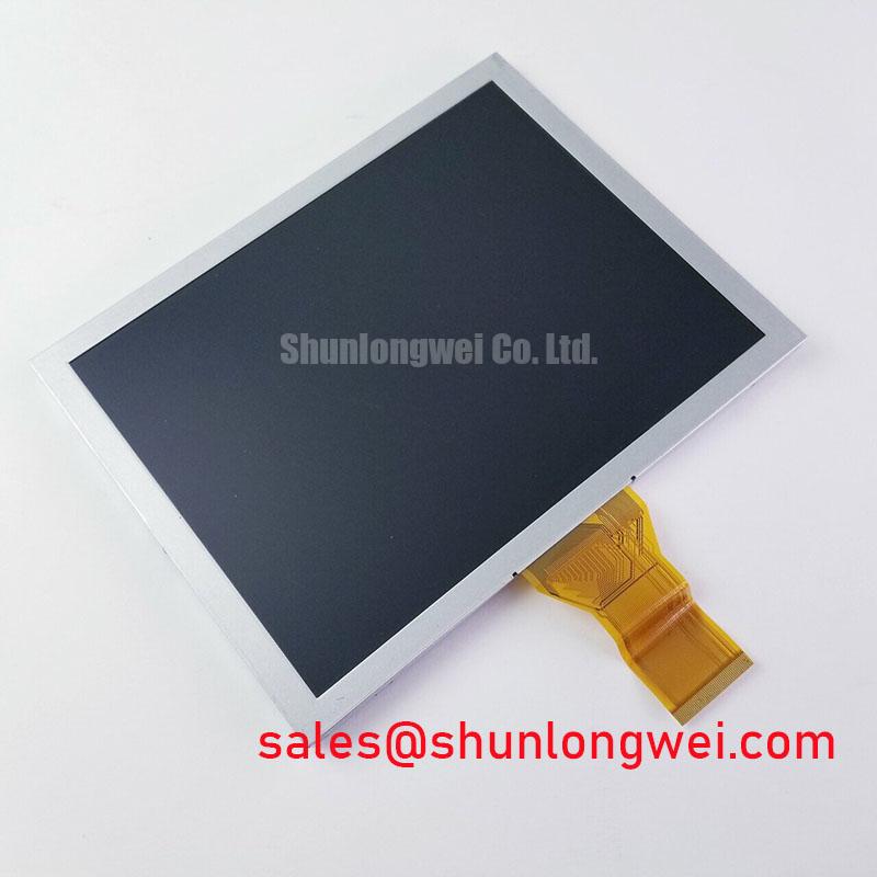
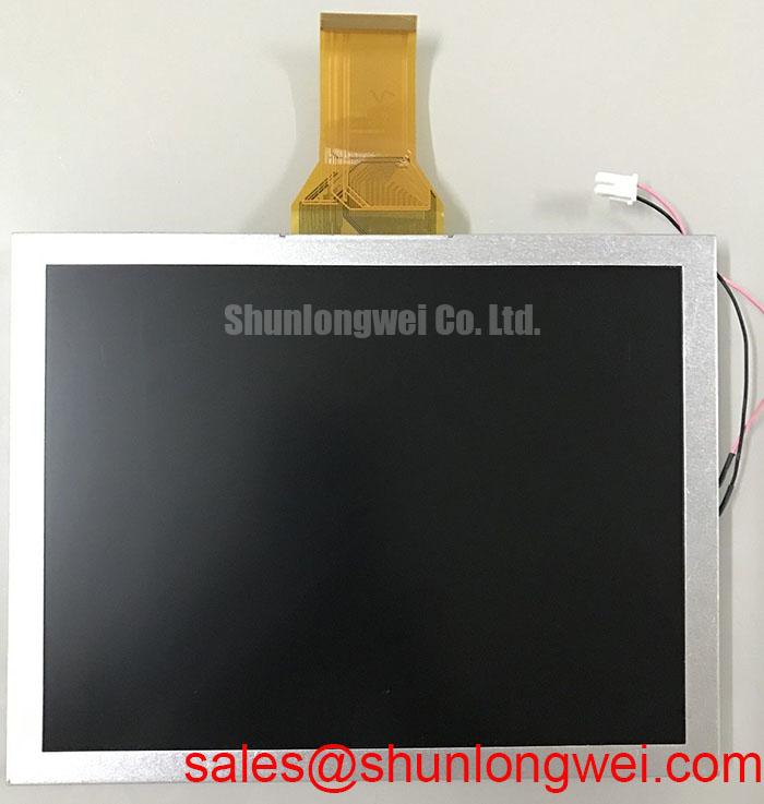
| Model | AT080TN52 V.3 |
| Manufacturer | Ampire |
| Product category | Industrial Grade LCD/HMI Panel |
| Display technology | TFT LCD Active Matrix Color Display Module |
| Specification status | Official Factory Spec Verified |
Measure the powered display across a repeatable full screen test pattern and record luminance uniformity, visible pixel defects, and color stability before investigating any backlight variation in the AT080TN52 V.3. A center point alone is not sufficient for incoming inspection because localized brightness differences can remain hidden until the panel is installed behind a machine bezel.
The Ampire unit is specified as a TFT LCD active matrix color display module. The supplied factory information does not establish a certified L70 or B50 half life, a specific LED backlight architecture, a guaranteed optical bonding construction, or a defined luminance value. Those characteristics should therefore be measured from the original panel documentation and the approved production sample rather than added to the product specification.
For an incoming quality check, use a uniform white field, black field, red, green, and blue screens, followed by medium gray patterns. Inspect the active area at normal viewing distance and under controlled illumination. A white field helps expose edge shading and broad luminance variation. Dark and gray fields are more useful for identifying residual images, line defects, intermittent pixels, and uneven light leakage. Keep the panel operating condition, warm up period, camera exposure, and viewing angle consistent between the incoming unit and the known good reference.
Thermal behavior should be assessed at the assembled product level. If the enclosure uses narrow aluminum rails or other heat spreading hardware near the display edges, treat that hardware as a Design Consideration, not as an Ampire factory parameter. The practical objective is to avoid localized heat accumulation near the active area and backlight region. The final rail geometry, contact pressure, insulation, and ventilation path must be determined by the equipment designer after checking the mechanical drawing and thermal test results.
Display timing also requires evidence from the host system. When a TTL or LVDS transmitter is used, verify clock quality, data setup, and data hold behavior over the actual machine temperature range. The panel model alone does not authorize a particular transmitter voltage, timing margin, connector assignment, or clock rate. Compare the signal at the panel interface with a known good assembly using an oscilloscope or suitable differential probe. A stable static image does not prove that high contrast transitions remain error free during temperature changes.
For a petrochemical Zone 2 operator station, the display should be evaluated inside the complete enclosure. A sealed window, gasket, cover lens, or optical bonding layer can change reflected light, heat transfer, and service access. If optical bonding is part of the finished HMI, verify moisture resistance and edge sealing through the system qualification plan; do not assume that the bare LCD module itself provides enclosure ingress protection.
Suppressing Pixel Jitter and Horizontal White Lines Near Motor Drives
Probe the display data path and compare the image fault with the switching activity of the nearby motor drive before changing the panel. Pixel jitter, horizontal white bands, or intermittent image loss can involve cable routing, reference potential movement, connector contact, host timing, or electromagnetic coupling, so the observed symptom should not be assigned to one cause without a controlled comparison.
Route the display cable away from high energy switching conductors where the machine layout permits, and inspect the connector for a fully seated, evenly aligned insertion. A shielded FFC or LVDS cable can reduce electric field coupling when its shield termination and chassis strategy are compatible with the host design. The correct termination depends on the cable construction and system grounding arrangement. A shield connected at an unsuitable point can create a new coupling path rather than remove the original disturbance.
Common mode filtering may be considered when differential signal quality remains stable but the complete cable assembly is exposed to strong common mode interference. The filter selection, placement, and impedance must be validated with the actual transmitter, receiver, cable, and enclosure. Do not treat a generic ferrite component as a guaranteed remedy for a horizontal noise band.
Some industrial display interfaces use controlled differential routing, but the official information supplied for this product does not confirm a 100 ohm differential impedance target, a specific skew limit, or a particular LVDS pin assignment for the AT080TN52 V.3. These values must come from the original interface documentation or the host equipment drawing. If the drawing specifies controlled impedance, inspect the complete path, including the board connector, FFC, transition region, and receiver termination, rather than measuring only a short exposed trace.
Use a known good cable and a stationary test image to separate mechanical contact faults from signal integrity faults. Gently apply controlled movement to the cable near the connector while observing the display, without stressing the panel glass or locking mechanism. An image change during this test may indicate an interface contact or cable retention issue, but it still requires visual inspection and continuity testing with power removed. Record whether the fault follows the cable, the host channel, or the display module.
For replacement evaluation, TCG084SVLQAPNN AN30 S may be reviewed as a separate same class display option when its mechanical envelope, interface, optical performance, and software timing are confirmed independently. Similar category or diagonal descriptions do not establish interchangeability. The engineer should compare connector location, mounting points, active area, viewing requirements, and power sequencing before approving any cross model substitution.
Managing Gray to Gray Response During Cold Start
Run a cold start test while recording the first image, gray transition behavior, residual image, and recovery time as the equipment moves from an unpowered condition to normal operation. This test should use the complete HMI assembly because the host controller, display timing, enclosure temperature, and backlight control can all affect the visible result.
Liquid crystal response can change with temperature, and a cold condition may make gray transitions appear slower or less uniform. That is a general display technology consideration rather than a published AT080TN52 V.3 response guarantee. Use repeatable gray test patterns and a photometric or high speed imaging method suitable for the required evaluation. Do not convert a visual impression into a numeric GTG specification unless the manufacturer’s technical documentation defines the measurement method and condition.
Check the power sequence at the display connector during cold start. The host should be evaluated for supply ramp behavior, display enable timing, data activity, and backlight activation. White screens, unstable images, or a brief residual frame can result from an unsuitable sequence, signal activity before the panel is ready, or a controller reset during supply transition. Capture the relevant rails and control signals with time correlation rather than replacing the panel immediately.
Long term static HMI screens also deserve a controlled inspection. Alternate fixed status pages with moving or changing test content during qualification, then check the screen for residual patterns under a neutral gray field. The supplied factory data does not provide a certified image retention limit or burn in endurance value for this model. The integrator should therefore define screen saver behavior, page rotation, brightness control, and service acceptance criteria from the application duty cycle.
Direct sunlight evaluation should use the actual cover glass, bezel, and enclosure. The supplied data does not verify a contrast ratio above 500 to 1 at 50,000 lux, nor does it confirm an anti glare coating. Measure readability and reflected luminance at the intended installation angle instead of assuming that a general industrial LCD label guarantees outdoor visibility. If a cover window is added, assess its surface reflection and seal design together with the display.
Perimeter sealing is also an assembly responsibility unless a specific sealed construction is documented by the manufacturer. Inspect the display edge, gasket compression, adhesive boundary, and enclosure interface after thermal cycling. Any epoxy or sealant used by the system builder should be qualified for adhesion, contamination control, and thermal movement. Do not infer the internal material or seal structure of the Ampire module from its external appearance.
💡 Bench Tip: Disconnect power before inserting or removing the display cable, protect the connector area against ESD, and engage the cable lock only after the FFC is fully aligned and parallel.
Backlight Isolation and High Voltage Interface Safety Checks
Separate the backlight supply from the display data test and measure the host output with the correct probe and isolation method before diagnosing acoustic noise, flicker, or a dark screen. The official information supplied for the AT080TN52 V.3 does not confirm CCFL ignition voltage, LED driver topology, PWM dimming ratio, backlight half life, MTBF, or secondary coil insulation ratings.
Do not apply a presumed 1500 to 1650 Vrms striking voltage to this model. Those values are not established as factory parameters for the product information provided. The system integrator should verify the required backlight supply and driver type from the original panel documentation. A constant current LED driver and a CCFL inverter require different electrical, mechanical, acoustic, and safety evaluations, and they must not be treated as interchangeable based on the display category alone.
When a high voltage backlight circuit is confirmed by the original equipment documentation, inspect insulation distance, cable routing, connector condition, shielding, and enclosure clearances under the applicable equipment safety procedure. High voltage testing is a system level activity requiring suitable instruments, controlled access, discharge verification, and documented limits. A display module should not be described as independently certified for the complete operator station, explosion protection, EMC, or insulation system.
If the equipment uses an LED driver, compare the enable signal, current regulation, dimming command, and audible behavior with the approved reference assembly. Flicker or buzzing may involve the driver switching behavior, mechanical resonance, mounting pressure, or an incompatible control signal. Verify the waveform at the driver input and output using measurement equipment appropriate to the circuit. Avoid selecting a replacement driver solely from a stated dimming ratio when the panel interface and thermal conditions have not been matched.
For a Zone 2 petrochemical operator station, the display is one element inside a certified enclosure and control architecture. The complete assembly may require separate assessment of sealing, temperature rise, cable glands, bonding, ignition risk, and hazardous area certification. The AT080TN52 V.3 product description identifies an industrial TFT LCD module, but it does not by itself certify the finished station for hazardous locations.
Engineering teams reviewing insulation behavior can consult the general references on partial discharge detection and silicone gel encapsulation for background concepts. These references do not constitute a product qualification for this Ampire display. For broader enclosure, interface, and environmental planning, the Industrial Display and HMI Solutions engineering guide provides additional system level context.
Use the manufacturer, model, TFT active matrix construction, connector arrangement, optical requirements, and verified host timing as the acceptance baseline for this LCD replacement. Any unconfirmed electrical, optical, thermal, or hazardous area characteristic should remain a system verification item rather than being presented as an AT080TN52 V.3 factory rating.