

Content last revised on October 8, 2026
Evaluating Thermal Capacitance vs Heat Sink Time Constant under Surge Bursts
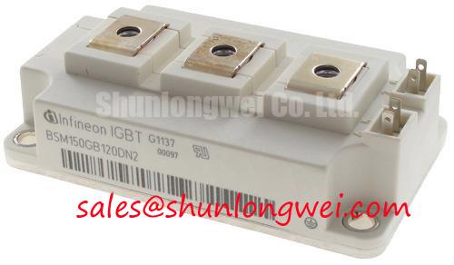
The Infineon BSM150GB120DN2 has the following Official Specification ratings. Their stated temperature conditions matter: the cold-case current rating is not a separate pulse-current allowance.
| Parameter | Official Specification | Engineering interpretation |
|---|---|---|
| Collector-emitter blocking voltage | 1200 V | Device blocking limit, not the permitted DC-link operating voltage |
| Continuous collector current | 150 A at case temperature 80°C | Conditional continuous-current rating |
| Continuous collector current | 210 A at case temperature 25°C | Cold-case continuous rating, not a startup surge specification |
| Collector-emitter saturation voltage | 2.5 V typical; 3.0 V maximum at junction temperature 25°C | Use the specified test current and gate conditions when comparing losses |
| Power dissipation per IGBT | 1250 W at case temperature 25°C | Conditional device limit, not guaranteed installed cooling capacity |
| Junction-to-case thermal resistance | ≤ 0.1 K/W | Steady-state thermal path; excludes the mounting interface and heat sink |
| Insulation test voltage | 2500 Vac for 1 minute | Test rating, not a continuous working-voltage declaration |
Design Consideration: Welding bursts and induction-heating load changes can raise junction temperature before the heat sink responds. Evaluate pulse losses against the manufacturer's transient thermal-impedance curves or validated thermal-network coefficients. A multi-RC model requires those coefficients and the actual loss waveform; steady-state thermal resistance alone cannot support a defensible peak-junction-temperature calculation.
Inspect baseplate contact, interface coverage, heat-sink flatness, and cooling flow when temperature rises unexpectedly. Compare measured case-temperature trajectories at equivalent loading rather than interpreting a cool heat sink as proof of a cool junction. Installation torque, interface thickness, and clearance requirements should come from the applicable mechanical documentation.
Long Motor Lead Reflected Wave Voltage & Motor Terminal Insulation Protection
Design Consideration: Long motor cables are a separate compatibility concern when this module is evaluated in motor-drive equipment; they are not an assumed feature of welding or induction-heating installations. Cable impedance mismatch and switching-edge propagation can increase motor-terminal voltage. Output-filter evaluation should use cable characteristics, motor insulation requirements, load current, and measured waveforms rather than a universal choke value.
For the specified welding and heating applications, first distinguish collector turn-off overshoot from load-side ringing. Measure at the relevant terminals with suitable probes and a controlled return path. Minimize commutation-loop inductance through closely coupled outgoing and return bus conductors, then verify switching peaks against the device's blocking limit over the intended operating range.
Gate-driver source and sink capability should be assessed from the documented gate-charge behavior and required switching timing. Reverse-transfer capacitance describes coupling; it is not interchangeable with Miller plateau charge. External gate resistance and any Miller-clamp arrangement should be evaluated through switching measurements, including unintended turn-on during opposite-device transitions.
💡 Pro Tip: Keep the gate-drive return separate from the high-current emitter path wherever the documented terminal arrangement permits, and verify the resulting gate waveform during switching tests.
Derating Guidelines and Mismatched Parameter Compensation in Parallel Operation
Design Consideration: Parallel operation requires matched electrical and thermal paths, not just matching nameplate current. Do not assume that saturation voltage has a favorable temperature coefficient throughout the operating range; confirm the relevant current-dependent curves before relying on temperature-assisted static sharing.
Dynamic balance also depends on gate-loop symmetry, driver timing, connection resistance, and cooling contact. If the official terminal drawing identifies an auxiliary emitter connection, assess its routing independently of the power-emitter connection. Do not infer a Kelvin terminal from the model designation. Measure individual branch current and switching behavior under controlled conditions before increasing load.
When comparing the BSM150GB120DN2 product details with FF150R12ME3G, treat the latter as a comparison candidate rather than an established direct replacement. Verify circuit configuration, terminal assignment, mounting dimensions, gate characteristics, diode behavior, and thermal limits against both manufacturers' documentation.
In equipment with a phase-controlled input rectifier, conduction angle and input-current harmonics belong to the rectifier and system-level assessment. Changing the IGBT module alone does not establish improved mains harmonic performance.
Calculating Failures-in-Time (FIT) Rates in High-Altitude Solar and Wind Farms
Design Consideration: Solar and wind installations introduce a separate reliability assessment, not a documented application qualification for this module. No model-specific FIT calculation, altitude threshold, or single-event-burnout probability can be established from the electrical ratings above. Such calculations require applicable manufacturer susceptibility data, an environmental model, operating-voltage history, and defined exposure conditions.
The Infineon OptiMOS low-voltage MOSFET portfolio and Infineon .XT technology article address different device families and technologies; neither establishes BSM150GB120DN2 cosmic-ray performance or internal construction.
For a failed installation, preserve fault logs and inspect switching overshoot, cooling condition, gate-drive integrity, and insulation contamination before assigning a mechanism. The Field Engineer’s Handbook provides supporting troubleshooting context. Any altitude-related derating decision should follow applicable manufacturer guidance and equipment-level validation, not an inferred percentage.

