

Content last revised on September 24, 2026
BSM200GB60DLC Replacement and Rating Verification
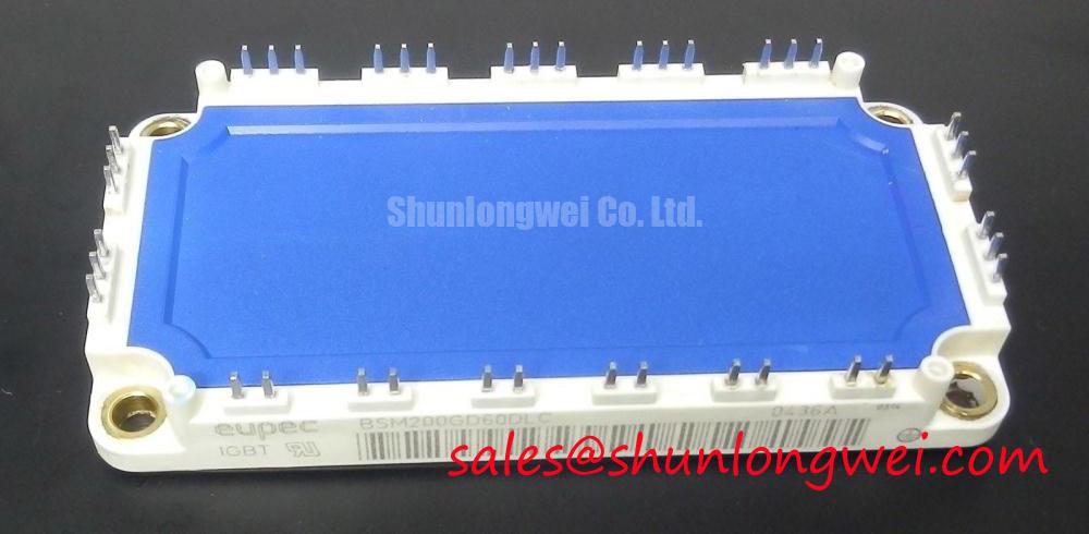
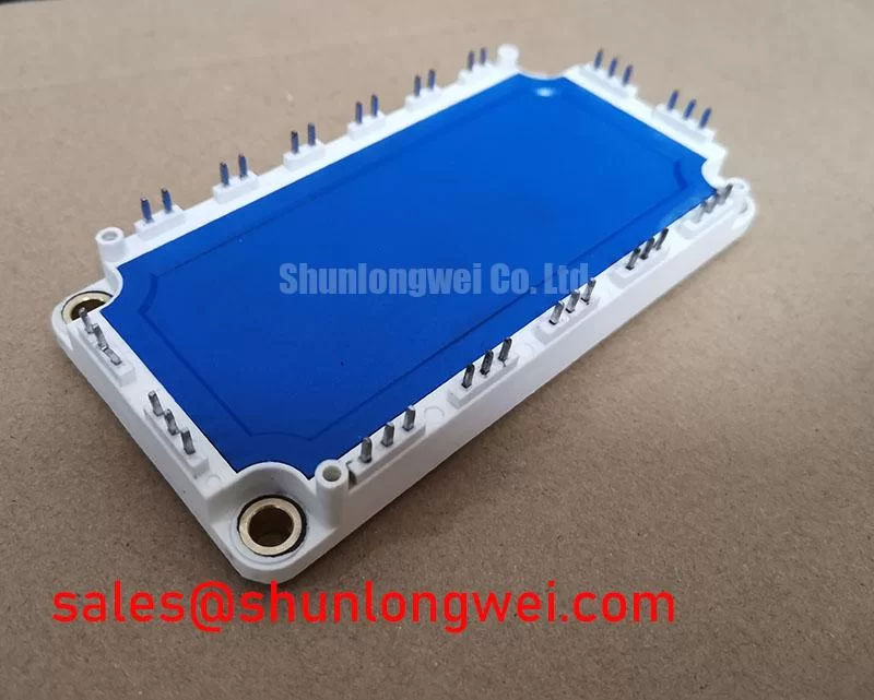
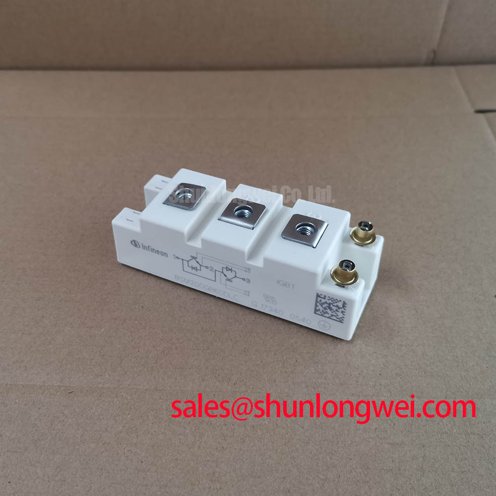
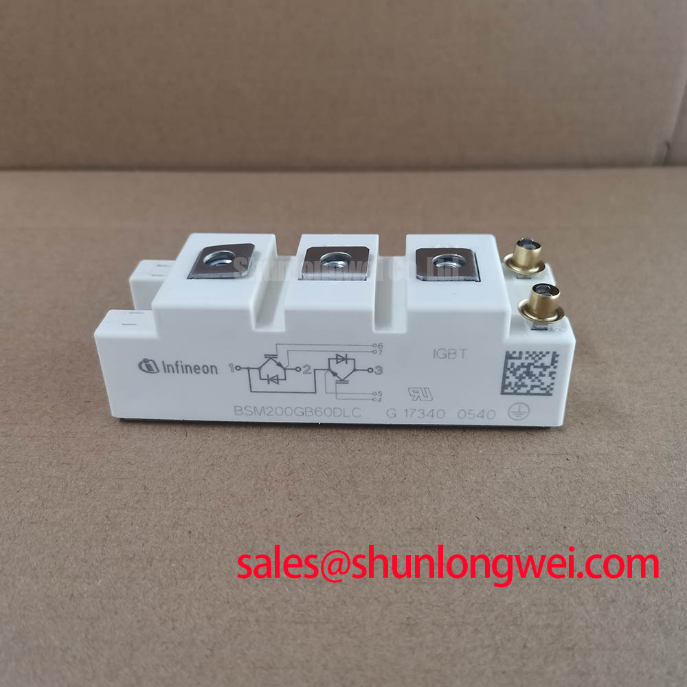
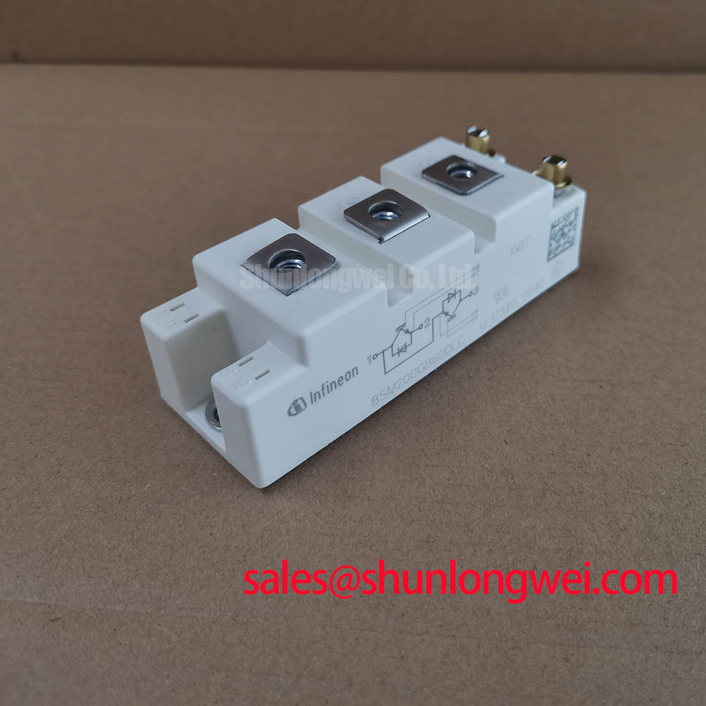
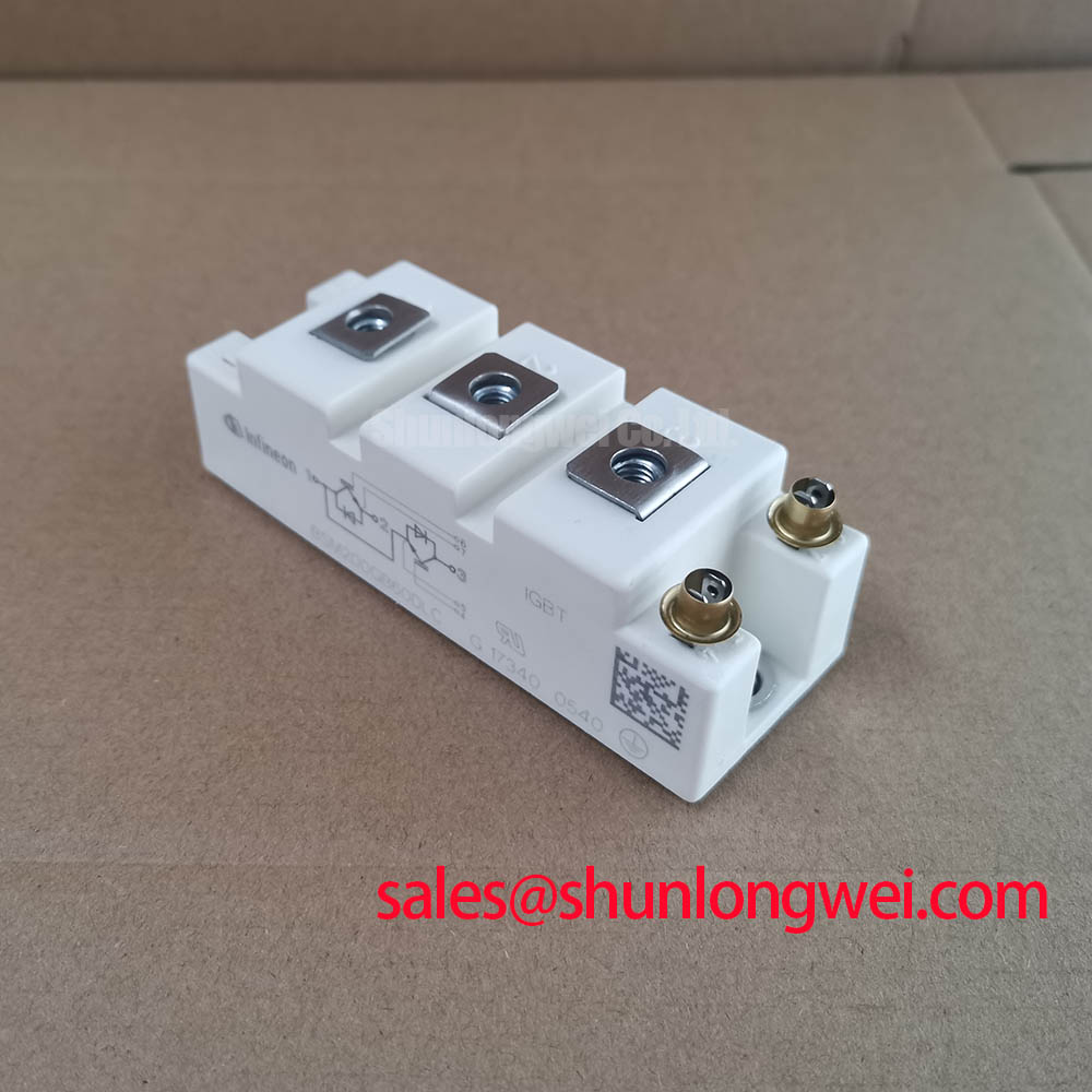
Before connecting a replacement module, verify the converter nameplate, isolate the DC link, and confirm that the installed device is marked BSM200GB60DLC with the required 600V and 200A ratings. These are Official Datasheet Specifications for this Infineon IGBT module. Compare the terminal arrangement, control connections, mechanical mounting interface, and conductor clearances against the removed assembly before applying any gate drive or DC bus voltage.
| Parameter | Value | Classification |
|---|---|---|
| Product model | BSM200GB60DLC | Official identification |
| Manufacturer | Infineon | Official identification |
| Collector emitter voltage rating | 600V | Official Datasheet Specification |
| Rated current | 200A | Official Datasheet Specification |
| Package | Module | Official Datasheet Specification |
The BSM200GB60DLC is a high voltage IGBT module for equipment in which the original electrical and mechanical interface requires this exact rating class. In a converter repair, voltage class alone does not establish interchangeability. Gate drive polarity, protection logic, terminal geometry, cooling interface, commutation path, and the surrounding converter topology must all be checked against the original equipment documentation.
BSM200GB60DLC Operational Boundaries: Evaluating Common-Mode Transient Immunity in Harsh Environments
The module itself is officially rated at 600V and 200A, but common mode transient immunity is principally a property of the complete drive arrangement rather than a published standalone property that should be assigned to the module without supporting documentation. The isolation barrier of the gate driver, its power supplies, signal routing, controller grounding method, and the physical position of high energy conductors all influence whether a switching event can disturb a command signal.
During commissioning, inspect the separation between the power bus and low voltage driver wiring. Keep gate command conductors away from collector and DC link conductors where practical, avoid long shared return paths, and ensure that cable shields or enclosure bonding follow the original converter architecture. This is a Design Consideration intended to reduce capacitive injection into sensitive control circuits during rapid switching transitions.
If a converter trips when pulse activity begins, do not assign the event to the IGBT module from one symptom alone. Capture the gate emitter voltage, DC link voltage, fault output, and controller command at the same time. A gate command that is absent at the driver input points toward control or interlock logic. A correct driver command accompanied by disturbance at the module terminals can indicate a return path, isolation, or layout issue requiring inspection.
For repair teams evaluating the BSM200GB60DLC in a full scale wind turbine converter, inspect enclosure bonding and high voltage cable routing as part of the installation review. Offshore and onshore equipment may place different demands on cabinet layout, environmental sealing, and service access. Those system conditions must be validated by the equipment integrator rather than inferred from the module rating.
Infineon’s IGBT Modules and Discretes portfolio provides useful manufacturer context for power semiconductor product families. It does not replace the original converter documentation, which remains the controlling reference for gate driver isolation and switching test requirements.
Preventing Spurious Faults: Optimizing Heatsink Contact Pressure and Mounting Guidelines for BSM200GB60DLC
Examine the heatsink contact area before installation. Remove hardened thermal interface residue, inspect for contamination and visible damage, and verify that the mounting surface is flat enough to establish uniform contact across the module base. A thermal interface material should be applied as a controlled, continuous layer without trapped voids. Thermal interface thickness is a Design Consideration and must be selected according to the heatsink, material supplier guidance, and the original equipment assembly practice.
Mounting screws should be tightened progressively in a balanced sequence so that clamp force develops evenly across the module. This helps avoid localized interface separation caused by an uneven fastening sequence. Use the module documentation and equipment service instructions for the applicable fastener and torque specification, because torque depends on the mechanical design and must not be assumed from a general module format.
💡 Pro Tip: Complete the mechanical fastening sequence before attaching power conductors, then recheck that no busbar force is twisting the module against the heatsink.
Gate drive sourcing and sinking capability should be evaluated as part of the converter system, not selected from current rating alone. The driver must charge and discharge the effective gate capacitance with sufficient control to produce repeatable switching behavior while the protection circuit remains able to respond to abnormal current. An external gate resistor can provide damping, but its value is a system determined tuning variable. Designers should verify turn on and turn off waveforms under representative load, temperature, DC link, and stray inductance conditions.
Where a repair assessment identifies an alternative family member, it should be compared by documented electrical limits, terminal configuration, driver requirements, and cooling fit. The BSM75GD120DLC is a separate IGBT module that can be reviewed as part of a documented compatibility study; its use should not be assumed as a direct substitute for the BSM200GB60DLC.
Benchtop Waveform Tuning: Mitigating Stress via PCB Symmetry Considerations for Dual IGBT on BSM200GB60DLC
Before energizing a repaired converter at operating voltage, check that each driver output returns through its intended reference path and that power current does not share a sensitive gate return conductor. Shared inductance can convert load current transitions into unintended gate voltage movement. This is especially relevant where a power module is connected to a driver board through harnesses, adapters, or extended terminal links.
A practical Engineering Recommendation is to make the outgoing and return conductors of each gate loop compact and closely coupled, while keeping high current commutation paths physically separate from the driver reference path. The aim is to reduce unwanted inductive voltage during switching. The correct geometry is dictated by the converter structure, module terminal arrangement, insulation requirements, and measured switching response.
Bench waveform work should begin with the converter’s approved reduced energy commissioning method. Observe collector emitter voltage, gate emitter voltage, and load current with probes connected according to safe high voltage measurement practice. Compare switching behavior between corresponding positions in the same converter where a known good reference is available. Ringing, unequal switching transition shape, or abnormal gate movement may indicate excessive loop inductance, inappropriate damping, probe connection effects, or a driver path defect. Each possibility should be isolated through measurement rather than treated as a single cause.
Dead time remains a system level control setting. It must prevent simultaneous conduction in the relevant converter leg while avoiding an unnecessarily extended interval that changes commutation behavior. The appropriate setting depends on the actual driver propagation characteristics, gate network, switching conditions, and control strategy. Engineers should validate it on measured waveforms rather than transferring a value from another module or converter platform.
For multi megawatt wind turbine full scale converter evaluations, busbar symmetry and balanced current return paths deserve specific attention. Large physical conductors can carry substantial switching current while their geometry introduces parasitic effects that are not visible in a static continuity test. Confirm peak voltage margins against the actual DC link during controlled switching tests before expanding operation.
BSM200GB60DLC Operational Boundaries: Evaluating Desaturation Detection Limits
Desaturation protection is implemented by the gate driver and surrounding sensing network, not by a generic assumption about the IGBT module. Its purpose is to identify an abnormal on state condition early enough for the drive system to remove gate charge in a controlled way. The required detection threshold, blanking behavior, response timing, and fault latching method must follow the converter design and the applicable driver documentation.
When investigating repeated desaturation events, inspect the gate drive supply integrity, desaturation sensing path, gate command waveform, DC link condition, load path, and module terminal connections. A fault response can arise from a genuine overcurrent event, an intermittent power connection, a sensing disturbance, inadequate gate drive, or a control sequence problem. Oscilloscope records taken during the event provide a more reliable basis for corrective action than replacing components by assumption.
Soft turn off behavior is also a system level protection function. If a serious fault is detected, an abrupt gate discharge can create inductive voltage stress in the power circuit. A staged response may be appropriate where supported by the original driver design, but the profile must be verified against measured collector emitter voltage and the full converter protection strategy. Do not alter protection timing or gate discharge behavior without confirming coordination with fuses, contactors, controller interlocks, and fault logging.
Semiconductor fuses must likewise be assessed through their published time current and energy characteristics in relation to the converter fault path. Their suitability cannot be concluded from a module current rating alone. The protection system should be reviewed as a coordinated assembly, including current sensing, desaturation detection, control shutdown, gate drive response, and available fault energy.
For a structured reference when reviewing switching behavior, protection interactions, and IGBT operating principles, consult The Ultimate IGBT Knowledge Base. Apply its principles alongside the original equipment schematic, approved service procedure, and measured converter waveforms.