
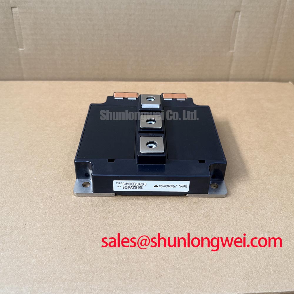
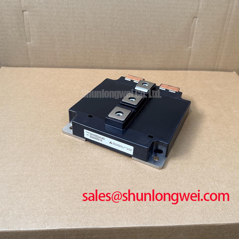
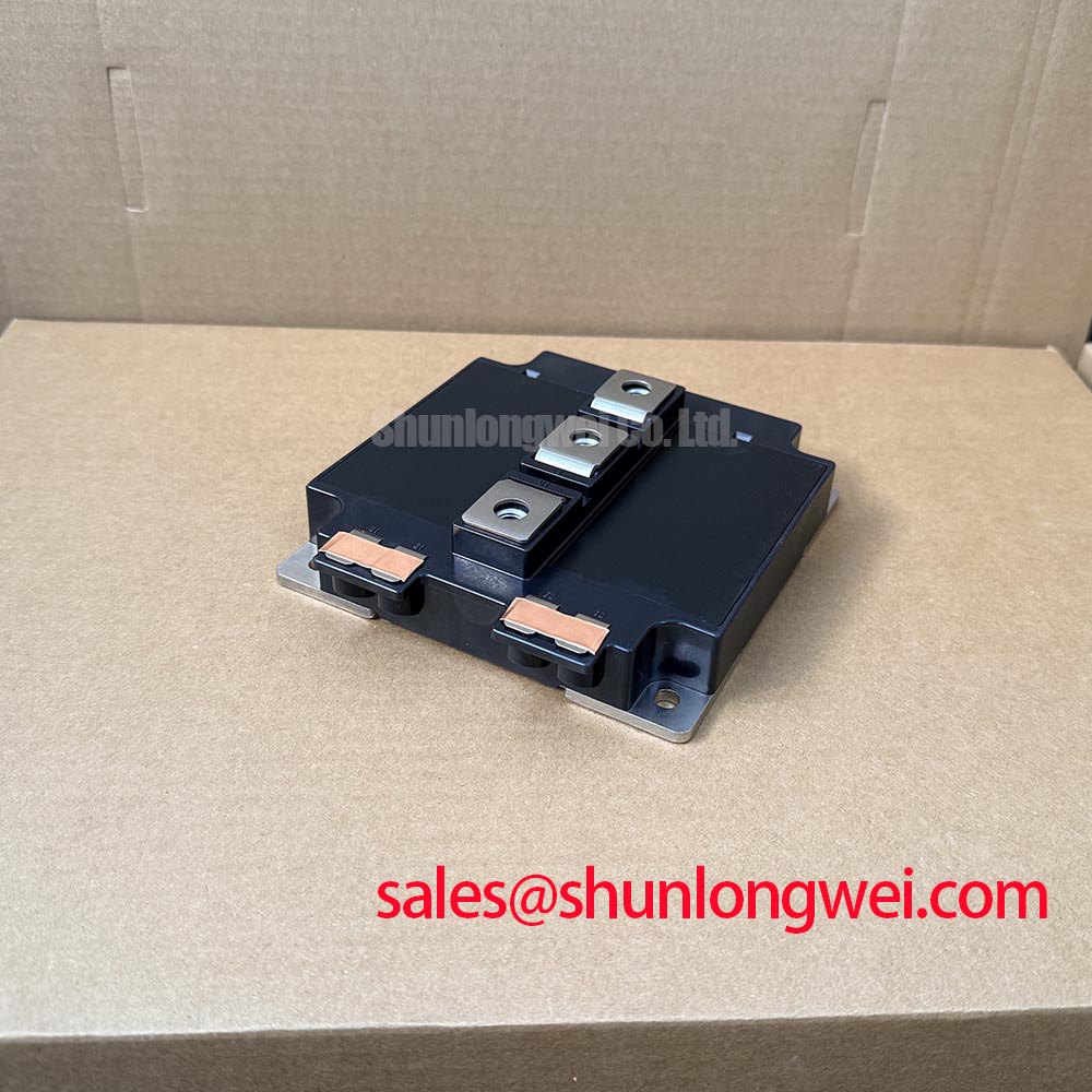



Content last revised on October 28, 2026
CM1000E2UA-24D Operational Boundaries: Evaluating High-Frequency Commutation Loop Inductance Limits
I trace the commutation path from the local DC-link capacitor through the switching stage and back before deciding whether a replacement module will resolve repeated overvoltage trips. With the equipment isolated and stored energy discharged, compare the installed busbar arrangement with the equipment drawing. Displaced conductors, missing connection hardware, or a capacitor connected through an extended return path deserve attention before powered testing.
Design Consideration: The relevant loop is the path carrying rapidly changing current, not simply the shortest visible connection between terminals. Closely coupled outgoing and return conductors can reduce loop inductance, provided the arrangement maintains the equipment’s required electrical clearances and mechanical support. A visually symmetrical busbar is not proof of balanced electrical paths; compare conductor overlap, terminal transitions, and capacitor connection geometry.
For an Engineering Calculation, the first-order turn-off voltage estimate is the DC-link voltage plus stray inductance multiplied by the current fall rate. This relationship explains why a mechanically convenient extension can increase voltage stress. It does not establish a universal inductance target: the acceptable loop depends on measured switching behavior, operating voltage, driver settings, and the applicable device limits.
During controlled switching tests, a qualified engineer should measure collector-emitter voltage using appropriately rated differential instrumentation and a probing arrangement that minimizes measurement artifacts. Evaluate peak voltage and ringing together with current and gate voltage. The 1200 V official voltage rating is a device boundary, not permission to operate the DC link at that voltage while ignoring switching overshoot.
If the existing design includes a snubber, inspect its connections and condition before changing capacitance. Increasing capacitance can alter pulse current, dissipation, and resonance; its final value belongs to the validated circuit design. The technical reference on Stray Inductance, Transient Voltage Overshoot provides supporting context for evaluating the relationship between interconnect geometry and measured switching stress.
A utility-scale 1500 V central solar photovoltaic inverter requires particular care during compatibility assessment: a 1200 V device must not be assumed suitable for blocking the full DC bus. Any evaluation must establish the actual topology, individual switch voltage exposure, voltage sharing, and transient behavior.
CM1000E2UA-24D Circuit Protection & Reliability: Calibrating Transient Thermal Impedance
Record case temperature, cooling-system condition, and the actual overload waveform before interpreting a thermal shutdown as a module fault. A case sensor responds differently from the semiconductor junction, so a modest measured case temperature does not establish adequate junction-temperature margin during a short, heavy load pulse.
Design Consideration: Transient junction-to-case thermal impedance describes the time-dependent temperature rise associated with device losses. For pulsed operation, the thermal assessment should use the applicable manufacturer curve or a thermal network fitted to that curve. A multi-RC model can represent this response, but arbitrary resistance and capacitance values cannot establish the thermal capability of the CM1000E2UA-24D.
For repeated overloads, the engineer should account for residual heating between pulses rather than treating every pulse as a cold start. Conduction loss, switching loss, pulse duration, and repetition pattern all affect the estimated junction temperature. Compare the resulting temperature excursion with the applicable junction-temperature limit and the equipment’s protection strategy; do not substitute the 1000 A official current rating for a thermal calculation.
When investigating temperature increases after a control-board change, compare the previous and current switching frequency, gate-drive behavior, and load profile. Higher switching frequency generally increases switching-loss contribution, but the resulting derating is system-dependent. Check fan operation, blocked heat-exchanger passages, coolant condition where applicable, and the temperature difference across the cooling path before attributing the change solely to the semiconductor.
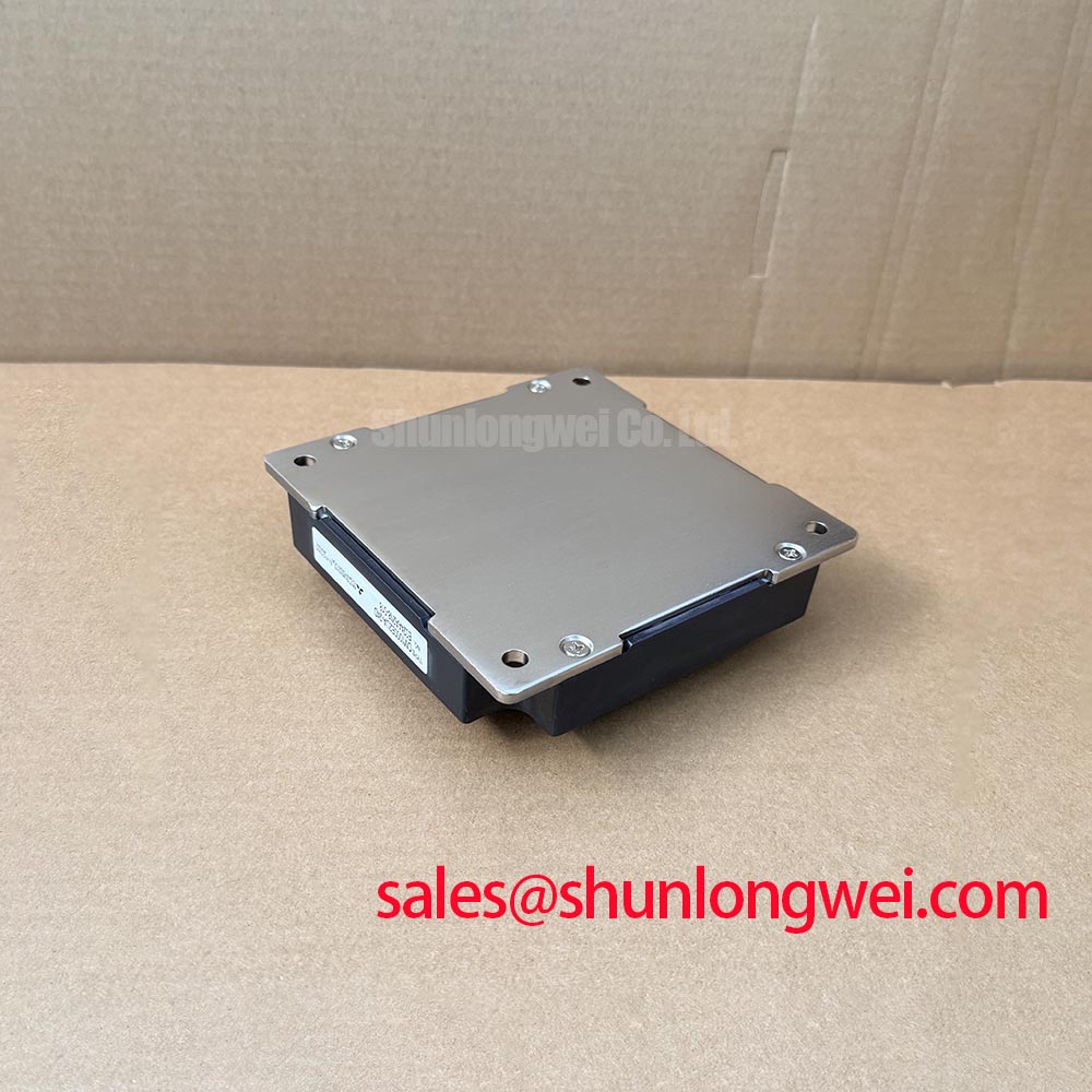
The mechanical inspection should follow the actual module and equipment assembly drawings. Pressure-stack calibration, disc-spring loading, and double-sided cooling procedures must not be transferred from a different package technology. At a specified module-to-heatsink interface, inspect surface condition and the approved thermal-interface material application; torque, tightening sequence, and interface thickness must follow the applicable assembly instructions.
Field Alert: Do not compensate for an uneven thermal interface by increasing bolt torque beyond the applicable assembly specification.
The Mitsubishi Electric Power Semiconductors & High-Power Modules resource is the manufacturer reference point for device documentation and application guidance. Keep the applicable thermal curves and mounting instructions with the repair work order so later measurements can be compared against the same conditions.
Transient Dynamics & Electrical Design: Desaturation Detection on CM1000E2UA-24D
Capture the gate command, collector-emitter voltage, and protection response on a common time reference when investigating a desaturation trip. A fault indication alone cannot distinguish a genuine overcurrent event from sensing-path interference, unsuitable blanking, or a driver-supply disturbance.
Design Consideration: Desaturation protection monitors whether collector-emitter voltage remains inconsistent with the commanded conducting state after the permitted turn-on interval. Its threshold is part of the driver circuit; it is not simply a copy of a nominal on-state voltage. Check the sensing diode path, associated components, driver reference connections, and routing against the equipment schematic.
A short circuit present at turn-on and a fault developing during conduction can produce different detection sequences. Blanking suppresses unwanted response during switching, but it also delays fault recognition. The combined sensing, propagation, and turn-off interval must fit the applicable short-circuit safe-operating conditions. Do not treat a generic response-time target as a verified withstand capability for this module.
Where the original driver uses staged or soft turn-off, preserve its intended sequence during repair. Slowing fault-current interruption can reduce inductive overshoot, while extending conduction also increases fault energy. The system engineer should validate that trade-off against the device’s applicable short-circuit limits and measured collector-emitter voltage. Repeated deliberate fault tests are not an appropriate preliminary diagnostic on a repaired power stage.
In material substitution reviews, the CM50MX-24A is a separate catalog device, not an established drop-in replacement for the CM1000E2UA-24D. Comparison requires matching electrical limits, circuit configuration, terminal layout, mounting geometry, thermal behavior, and driver requirements. A shared manufacturer or voltage class does not establish interchangeability.
For adjacent power stages, identify the actual rectifier, DC-link, and switching functions from the schematic. The separately listed CM200DU-24H can be considered in a broader component review, but its catalog presence does not establish a rectifier function or compatibility with this module. Fault coordination depends on the installed circuit and its protection paths.
Preventing Spurious Faults: Thermal Stress Monitoring across High-Current Guidelines for CM1000E2UA-24D
Measure suspect bolted connections with a four-wire micro-ohmmeter after isolating the assembly and establishing a safe test condition. An ordinary continuity check cannot resolve the small resistance changes that matter in a high-current joint. Position the voltage-sense contacts consistently so comparisons represent the joint rather than different lengths of conductor.
Design Consideration: Compare equivalent joints at similar temperatures and account for parallel current paths that could distort the measurement. Use the equipment manufacturer’s acceptance criteria rather than assigning a universal contact-resistance threshold. Record probe locations, joint temperature, instrument configuration, and connection condition so a later measurement has diagnostic value.
Under an approved operating test, thermography can help identify uneven heating across comparable terminals. Interpret the image alongside current distribution, cooling airflow, surface emissivity, and reflections from exposed metal. A hotter connection warrants investigation, but the image alone cannot distinguish poor contact from unequal loading or nearby heat transfer.
After correcting a connection, repeat resistance measurement and thermal observation under comparable conditions. Check busbar alignment, supported cable loading, specified washers, and thread condition before final tightening. Keep the recorded electrical and thermal observations with the equipment identifier and repair date; that comparison is more useful for the next service visit than an unsupported claim about remaining operating life.