
Content last revised on October 23, 2026
Assembly Integrity and Layout Architecture for CM100E3U-24F
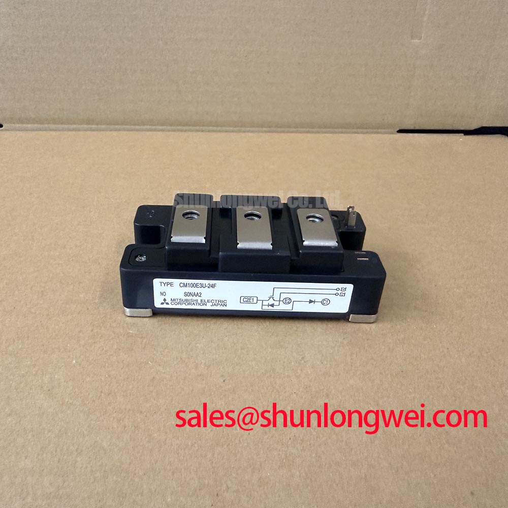
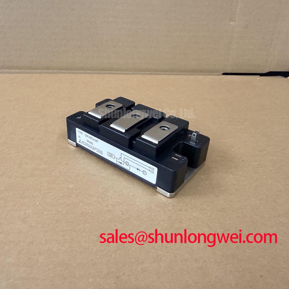
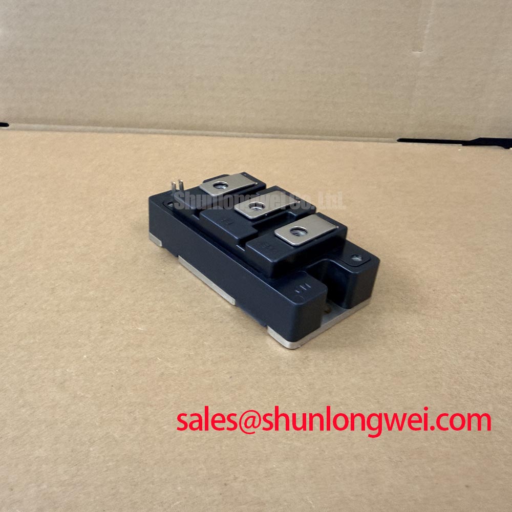
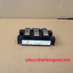
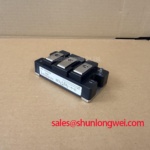
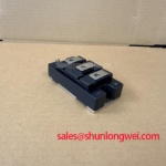
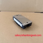
When a commercial string inverter reports abnormal DC link ripple or repeated power stage trips, isolate the converter section before energizing the battery racks. Confirm the module marking, inspect the main terminals for mechanical damage, and compare the cold electrical condition with a known service reference. The Mitsubishi CM100E3U-24F is an IGBT Module with an official rated voltage of 1200.0 V and an official rated current of 100.0 A; its listed package is Module.
In a bidirectional battery inverter, the power path can reverse as the system changes between battery charging and DC bus support. That four quadrant operating pattern makes commutation behavior, current sharing, and thermal cycling important during peak shaving. The module rating identifies its voltage and current class, but the complete operating boundary remains dependent on switching frequency, cooling, gate drive conditions, modulation strategy, and the qualified thermal design.
For interleaved DC to DC converter sections, keep each phase current loop physically compact and route the positive and return conductors as a closely coupled pair. Ripple current should remain within the intended copper path rather than spreading through control ground, sensor returns, or cabinet sheet metal. This is a Design Consideration, not a Mitsubishi guaranteed layout value. The system designer should establish the required clearance and creepage from the actual working voltage, insulation system, pollution environment, and applicable equipment standard.
During commissioning, inspect the laminated busbar interfaces, insulating supports, and copper overlap around the module terminals. Uneven support can introduce mechanical stress while also increasing the effective commutation loop. At turn off, stray inductance converts rapid current change into a voltage overshoot. The practical control method is to minimize the high di/dt loop, place the local film capacitor close to the switching path, and verify the peak voltage with a properly referenced differential probe during controlled switching tests.
Interleaving reduces input and output ripple only when the phase timing and current sensing remain consistent. If one phase develops a different switching delay, a loose terminal, or a degraded gate connection, the remaining phase may carry a disproportionate share of the ripple current. Check gate signal symmetry at the driver output and at the module terminals, then compare phase current waveforms under the same test condition. A visible difference does not identify one single failed component; it directs the investigation toward drive timing, current measurement, busbar geometry, and thermal coupling.
The antiparallel diode deserves attention when the inverter changes current direction. Reverse recovery softness is often discussed through a softness factor, but that value should not be assigned to this module without the applicable manufacturer switching data and test conditions. A hard recovery signature can increase common mode voltage movement and radiated EMI, while a soft recovery profile can still produce unacceptable losses if the commutation loop or gate timing is poorly controlled. Evaluate reverse recovery current, voltage overshoot, and conducted or radiated emissions as a complete switching network rather than treating the diode rating as an EMI guarantee.
For cross reference work, engineers may review the electrically different CM400HU-24H as a separate Mitsubishi module listing. It should be assessed from its own topology, ratings, terminal arrangement, thermal conditions, and mechanical envelope rather than treated as an automatic replacement for the CM100E3U-24F.
CM100E3U-24F Circuit Protection and Reliability Screening
Cold unpowered screening should begin with the DC link fully isolated and the module disconnected from the driver and capacitive energy sources. Use the digital multimeter diode function to examine the main conduction paths in both polarities, including the antiparallel diode path identified by the module’s terminal diagram. Record the meter indication, test lead polarity, ambient condition, and connection points. A diode reading is a comparative screening result, not a substitute for the manufacturer’s dynamic switching characterization.
Before measuring, discharge connected capacitors through the approved service circuit and confirm the absence of residual voltage with an instrument suitable for the equipment category. Do not rely on the inverter display or control board status alone. The main terminals should be checked for an unexpected short indication, an open path where a semiconductor path is expected, or a reading that differs materially from a known-good reference tested with the same meter.
Gate leakage screening requires the gate terminal to be separated from the driver output and measured against the appropriate emitter reference shown in the original connection documentation. Keep the test voltage low and controlled according to the approved device test method. A high or unstable leakage indication may result from contamination, a damaged gate structure, a connected driver component, or an incorrect terminal reference. Repeat the measurement after isolating the external circuit before assigning the result to the module.
🔧 Bench Diagnostic: Use ESD protection, short the gate to its specified reference before handling, and record a cold baseline before applying any DC bus voltage.
Protection coordination should combine the module with the actual DC link capacitor, local film snubber, busbar, gate driver, and upstream surge network. The snubber capacitor must be mounted close enough to control the commutation loop that its lead inductance does not defeat its purpose. The required capacitance, voltage rating, damping method, and physical placement are system design decisions established through switching measurements.
A MOV may be used as part of a broader overvoltage absorption network, but its clamp behavior, energy capability, repetitive duty, and coordination with the DC link protection must be verified for the complete inverter. It should not be presented as a standalone guarantee against switching overshoot. The same principle applies to active clamp circuits and desaturation protection: each must be tested with the real gate resistance, driver supply, current path, and fault timing.
The Mitsubishi Electric CSTBT™ technology information provides useful manufacturer context for Mitsubishi power semiconductor technology, but it does not replace the specific electrical and switching conditions applicable to this part number. When a system includes a separate thyristor stage, its IGT and VGT requirements belong to that thyristor’s documentation. They should not be transferred to the IGBT module. Strong triggering pulse trains may be appropriate for a qualified thyristor controller, while the CM100E3U-24F requires the gate drive conditions defined for its own device family and circuit.
For maintenance teams building a repeatable incoming test record, capture the part marking, terminal identification, diode-check direction, gate leakage result, ambient temperature, and instrument model. The Field Engineer’s Handbook can support broader test planning for field analysis, while the acceptance limits for this specific module should remain tied to the applicable device documentation and the equipment repair procedure.
Preventing Spurious Faults Through Main Terminal Contact Control
Bolted terminal quality has a direct effect on heating, voltage measurement, and apparent current imbalance. Inspect the mating surfaces, busbar flatness, insulating hardware, and fastener condition before tightening. A micro-ohmmeter test should be made across the complete joint, with the measurement probes positioned so that the result includes the actual contact interface rather than only the copper bar.
Use a four-wire measurement method and compare each power terminal under the same mechanical condition. The project acceptance limit, including any low-micro-ohm requirement, should come from the qualified assembly procedure rather than from a generic value applied to every module. Repeat the measurement after mechanical rework, because a visually clean joint can still show unstable resistance when clamping pressure is uneven.
Thermographic inspection should be performed after the assembly reaches a stable and documented load condition. Compare corresponding terminals, busbar transitions, fuse interfaces, and adjacent phases. A warmer terminal may reflect contact resistance, current imbalance, airflow variation, sensor placement, or an unequal thermal path. Use the thermal image to locate the investigation area, then confirm the condition with electrical measurement and mechanical inspection.
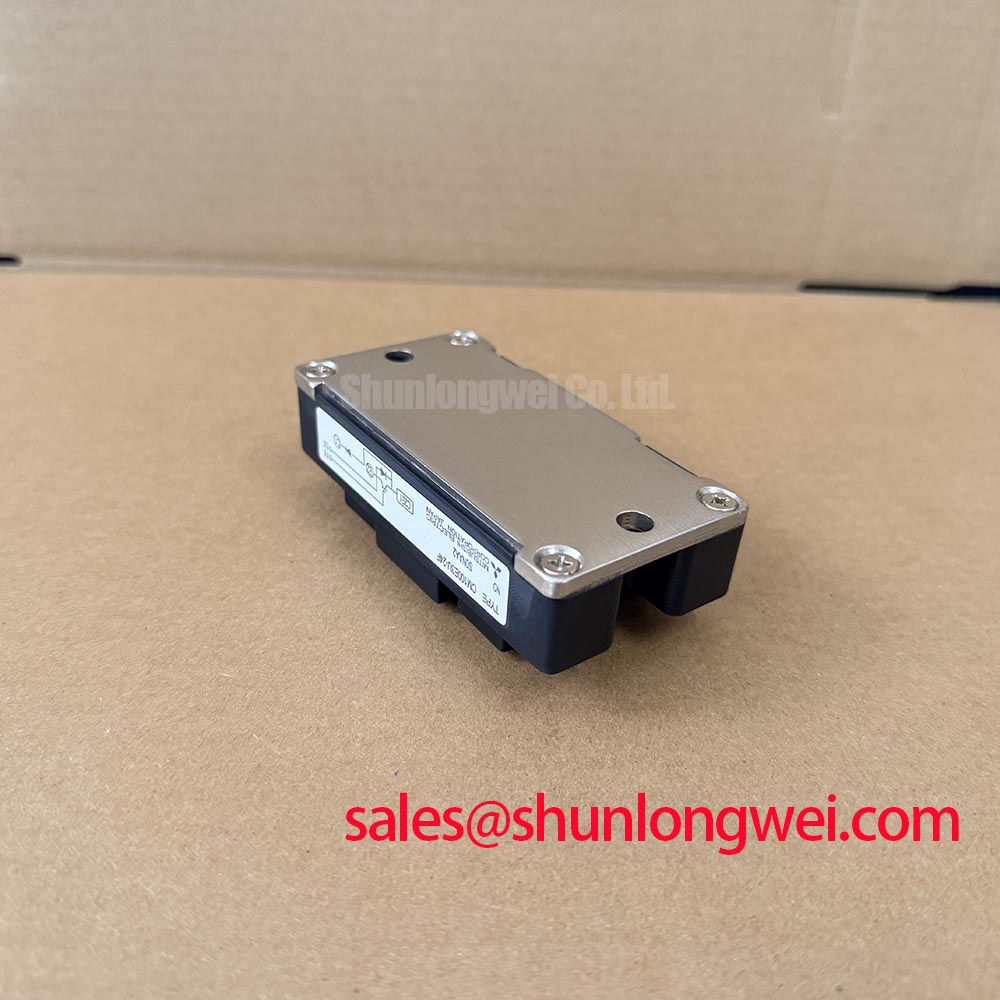
Where double-sided cooling is used, both heat transfer surfaces must remain flat, clean, and uniformly loaded. A thin, continuous thermal interface layer is preferable to excess compound that can create mechanical variation. Clamping hardware, spring washers, or disc springs should be calibrated through the equipment manufacturer’s assembly method so that pressure remains distributed across the module base. The correct installation force is not inferred from the 100 A rating.
Repeated heating during battery charge and discharge can change joint condition over time, especially when the busbar and heatsink expand at different rates. Trend the terminal temperature and micro-ohmmeter result during scheduled service rather than waiting for a protection trip. If the thermal profile changes while semiconductor diode screening remains comparable, examine the external joint, current distribution, cooling path, and sensor mounting before condemning the module.
In a commercial micro-grid cabinet, the CM100E3U-24F may be evaluated for a replacement or repair position in a string inverter power stage, subject to the original circuit topology, gate-drive compatibility, cooling arrangement, insulation coordination, and mechanical fit. Procurement and repair personnel should match the exact Mitsubishi part number and terminal configuration before release to service.