


Content last revised on March 28, 2026
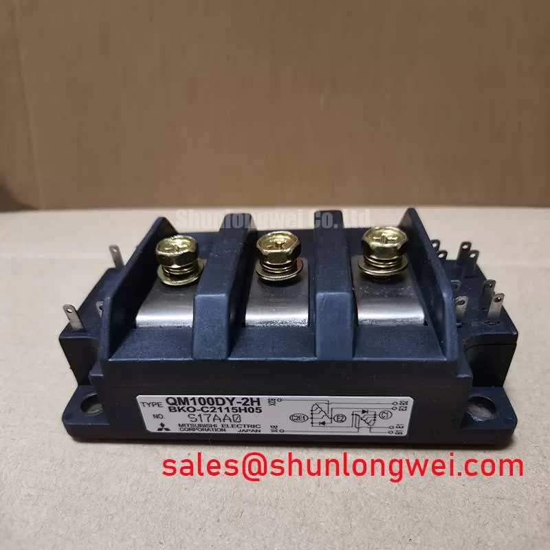
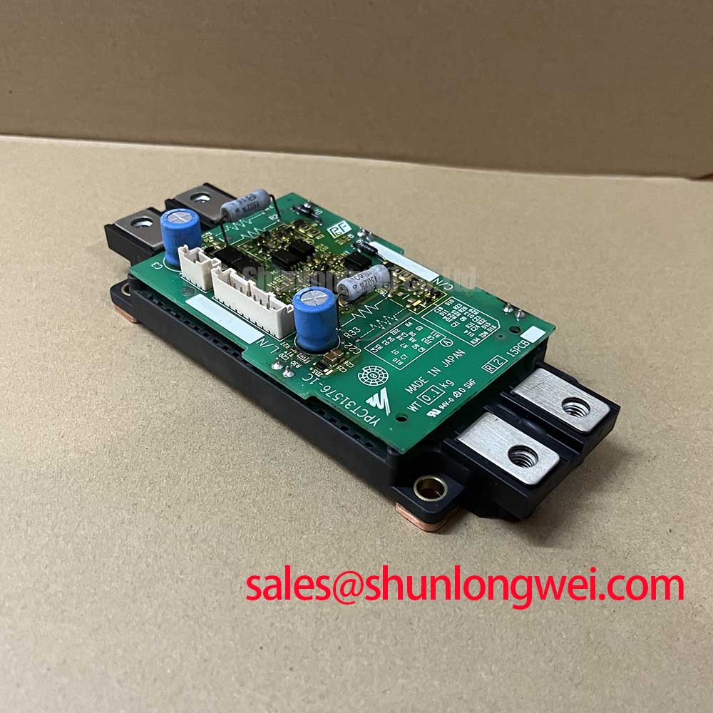
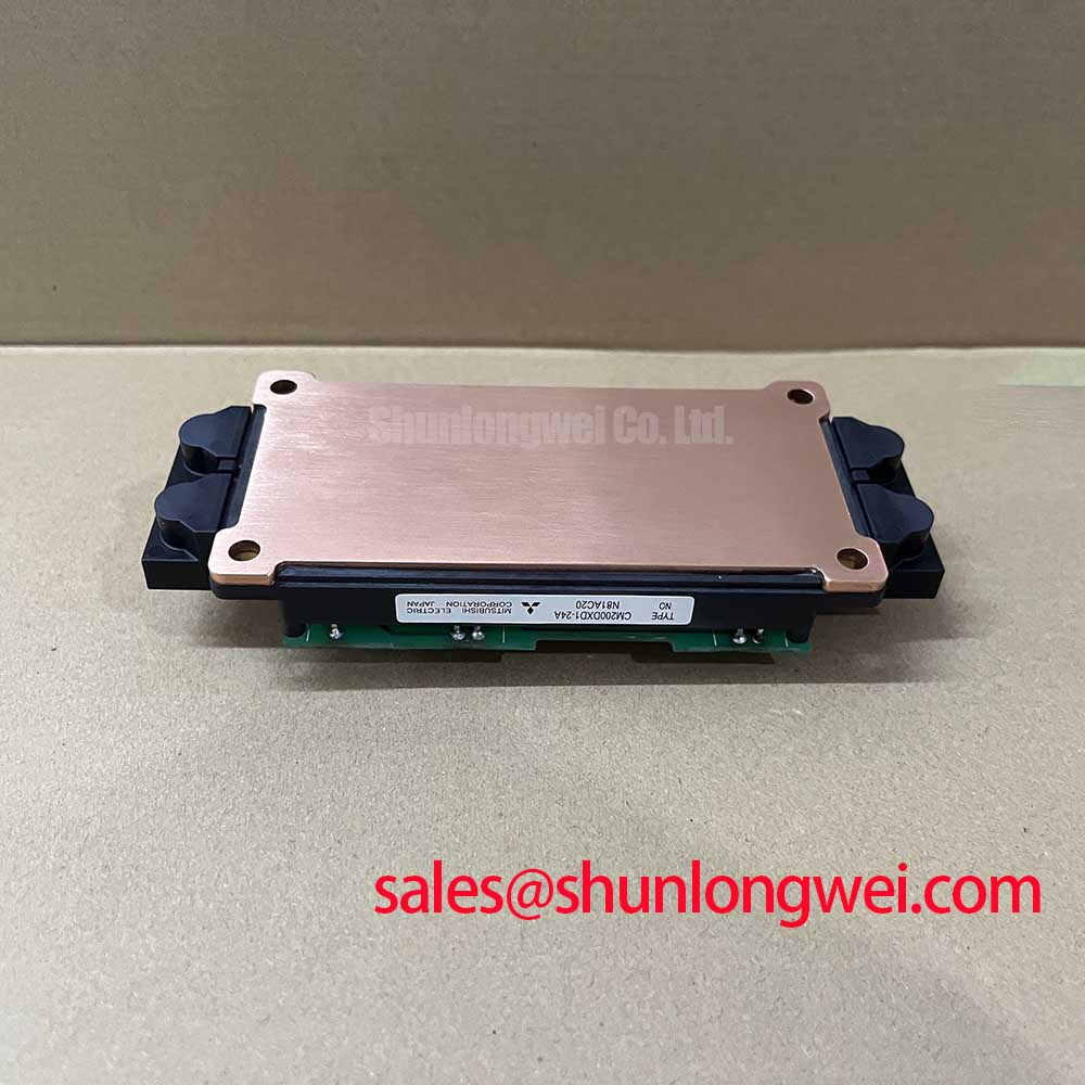
CM200DXDX1-24A | 1200V 200A Dual IGBT Module Technical Review
Introduction and Feature Overview
The Mitsubishi CM200DXDX1-24A is a dual IGBT module engineered for high-efficiency power conversion, offering a precisely defined balance between low conduction losses and controlled switching performance for demanding industrial inverter applications. With core specifications of 1200V and 200A, and a typical VCE(sat) of just 2.2V, this module provides a robust foundation for power stage design. Key engineering benefits include significantly reduced thermal load and a streamlined half-bridge layout. For engineers designing industrial drives, this module directly addresses the challenge of maximizing system efficiency by minimizing conduction losses, a critical factor in overall performance and reliability. For mid-power industrial drives up to 100kW, the CM200DXDX1-24A is an optimal choice for achieving high efficiency with a simplified thermal design.
Application Scenarios & Value
Driving Efficiency and Reliability in Industrial Inverters and Drives
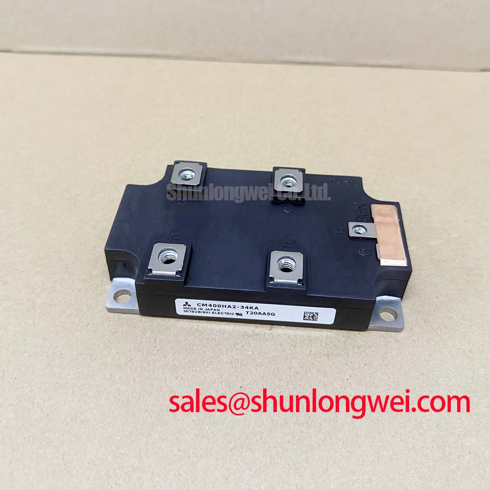
The CM200DXDX1-24A is primarily engineered for the core of medium-power industrial motion control and power conversion systems. Its dual-IGBT, half-bridge configuration makes it a fundamental building block for three-phase Variable Frequency Drives (VFDs) and Servo Drives. In a typical 75kW VFD application, the primary engineering challenge is managing the heat generated by the power semiconductors. The module's low collector-emitter saturation voltage of 2.2V (VCE(sat)) at its nominal 200A rating directly confronts this issue. This low on-state voltage minimizes power dissipated as heat during conduction, which allows designers to specify smaller, more cost-effective heatsinks and potentially increase the overall power density of the inverter cabinet. This efficiency is also critical in applications like Uninterruptible Power Supplies (UPS) and welding power sources, where reliability and minimizing energy waste are paramount. For systems requiring higher current handling capabilities within a similar package, the related CM300DX-24A offers an increased rating of 300A.
Key Parameter Overview
Analyzing the Electrical and Thermal Specs for Loss Calculation
The performance of the CM200DXDX1-24A is defined by a set of critical electrical and thermal parameters. These specifications are essential for accurate system modeling, loss calculation, and ensuring long-term reliability.
| Parameter | Symbol | Conditions | Value |
|---|---|---|---|
| Collector-Emitter Voltage | VCES | VGE = 0V | 1200V |
| Collector Current (DC) | IC | TC = 80°C | 200A |
| Collector Current (Pulse) | ICM | Pulse width ≤ 1ms | 400A |
| Collector-Emitter Saturation Voltage | VCE(sat) | IC = 200A, VGE = 15V | 2.2V (Typ.) / 2.7V (Max) |
| Gate-Emitter Voltage | VGES | - | ±20V |
| Turn-On Delay Time / Rise Time | td(on) / tr | IC = 200A | 150ns / 50ns (Typ.) |
| Turn-Off Delay Time / Fall Time | td(off) / tf | IC = 200A | 500ns / 200ns (Typ.) |
| Thermal Resistance (Junction-to-Case) | Rth(j-c) | IGBT | 0.14 °C/W (Max) |
| Operating Junction Temperature | Tj | - | -40 to +150°C |
Parameter Interpretation:
- VCE(sat): This parameter is a direct measure of the module's efficiency during the 'on' state. The low typical value of 2.2V means less power is converted into waste heat, a critical factor for achieving higher overall system efficiency and reducing the burden on the cooling system.
- Rth(j-c): The thermal resistance from the semiconductor junction to the module's case is a crucial indicator of how effectively heat can be extracted. Thinking of it like the diameter of a pipe, a lower Rth(j-c) value, like the 0.14 °C/W of this module, signifies a wider pipe allowing heat to escape more easily. This enables the device to run cooler under load, which is fundamental for improving system reliability and lifespan.
Technical Deep Dive
Deconstructing the Balance Between Conduction and Switching Losses
A successful power electronic design hinges on managing the trade-off between conduction and switching losses. The CM200DXDX1-24A datasheet provides the necessary data to navigate this balance effectively. While the low VCE(sat) minimizes conduction losses, the switching characteristics (td(on), tr, td(off), tf) dictate the energy lost during the transitions between on and off states. The typical total turn-on time of 200ns and turn-off time of 700ns are key inputs for any accurate switching loss calculation. For applications like a Variable Frequency Drive (VFD) operating at a common frequency of 8kHz, these parameters allow engineers to predict thermal performance with high confidence, ensuring the junction temperature remains well within its safe operating area. The use of advanced chip technology, like Mitsubishi's CSTBT™, is central to achieving this optimized balance, enabling robust performance without excessive heat generation.
Frequently Asked Questions
How does the 2.2V VCE(sat) of the CM200DXDX1-24A benefit thermal design in a VFD?
A lower VCE(sat) directly reduces conduction power loss (P = VCE(sat) x IC). At 200A, this module dissipates less energy as heat compared to a device with a higher VCE(sat). This reduction in waste heat simplifies thermal management, potentially allowing for a smaller heatsink, reducing system size, weight, and cost while improving reliability.
What is the primary benefit of its low VCE(sat)? Reduced power loss and lower operating temperatures.
What is the significance of the dual (half-bridge) configuration in this module?
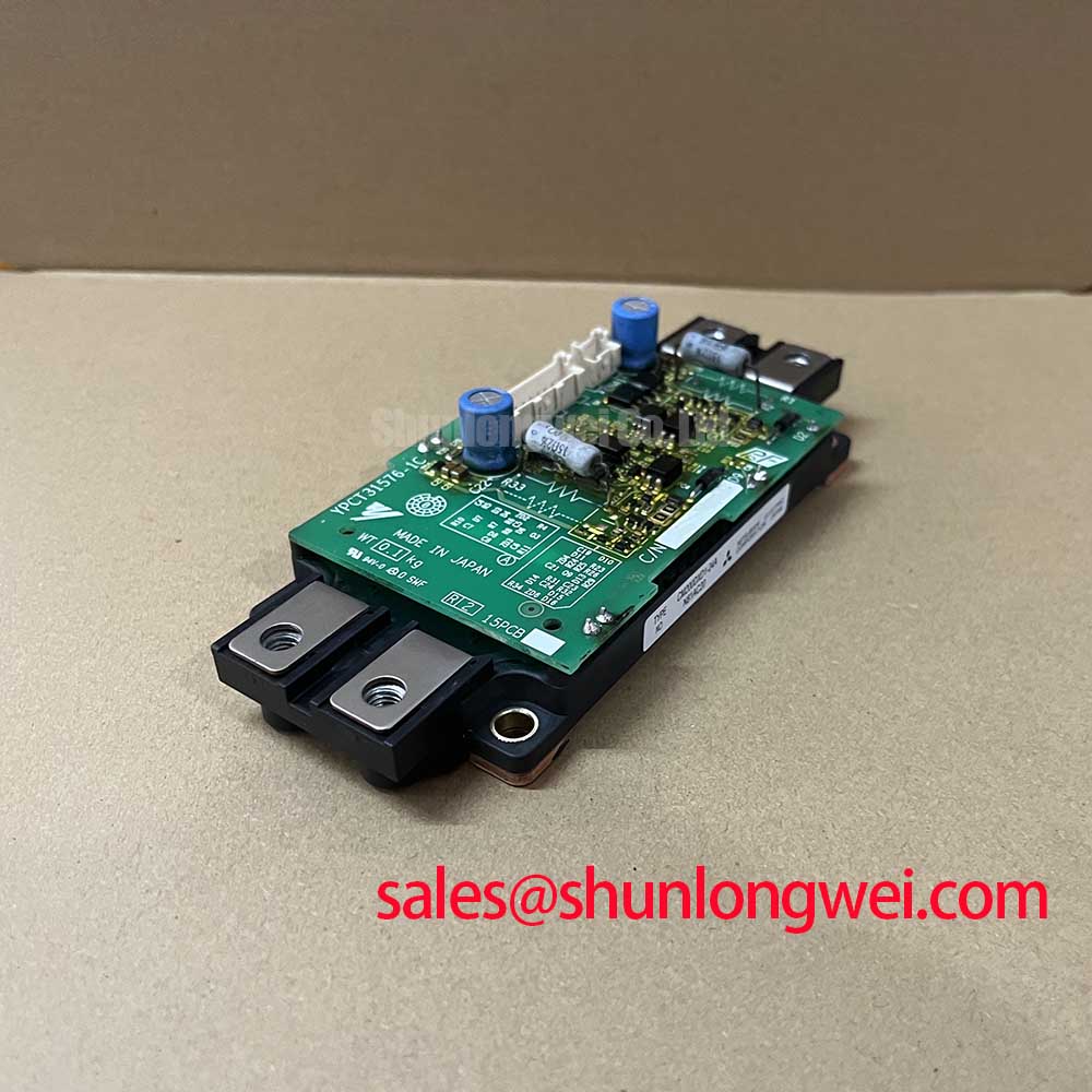
The dual IGBT configuration provides two switches in a single package, which is the standard arrangement for one phase leg of a three-phase inverter. This integration simplifies the Power Board layout, reduces stray inductance between switches, and streamlines the manufacturing assembly process compared to using two discrete IGBT components.
The datasheet specifies switching times at a certain condition. How should I adjust my loss calculations for different operating points?
The datasheet provides performance curves showing how switching energies (Eon, Eoff) vary with collector current and gate resistance. Engineers must use these graphs to extrapolate the values for their specific operating conditions. This ensures a more accurate estimation of total switching losses and, consequently, a more precise thermal simulation for the application.
Engineering and Procurement Inquiries
To evaluate the CM200DXDX1-24A for your power system design or to inquire about procurement, please contact our technical sales team for expert consultation and support.