Content last revised on September 10, 2026
CM25MD-24H Thermal Electrical Optimization for Regenerative DC Bus Voltage Surge Dissipation
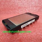
With the drive fully isolated and the DC link confirmed discharged, begin by comparing cold terminal to terminal readings against the removed module and a known good circuit position before installing the CM25MD-24H. This Mitsubishi Electric power module is rated at 1200 V and 25 A as an Official Datasheet Specification, with a Module package. Those ratings establish the electrical identity to verify during a repair assessment, but they do not by themselves confirm the original converter topology, gate drive conditions, thermal interface, or protection settings.
Inspect the case, power terminals, control terminals, mounting contact area, busbar alignment, and surrounding PCB before applying power. A low resistance reading where the installed circuit should be isolated, damaged terminal hardware, uneven mounting pressure, or carbon tracking near the bus connection can each affect the repair outcome. Use the original drive documentation to identify the module position and the expected switching function before treating this unit as a direct circuit replacement.
| Manufacturer | Mitsubishi Electric |
| Product model | CM25MD-24H |
| Voltage rating | 1200 V Official Datasheet Specification |
| Current rating | 25 A Official Datasheet Specification |
| Package | Module Official Datasheet Specification |
In a multi axis CNC or robotics servo cabinet, rapid motor deceleration can return mechanical energy to the DC bus. Before assigning the CM25MD-24H to any braking function, trace the actual power path from the DC link through the braking resistor assembly, chopper circuit, drive control board, and feedback wiring. The model designation and the stated 1200 V, 25 A ratings should not be used to infer whether this specific module is the braking switch, an inverter leg, or another power stage. The original schematic and terminal mapping remain the governing references.
Design Consideration: regenerative energy must be handled by the complete system arrangement rather than by a module rating alone. The braking resistor must have a duty capability appropriate to the deceleration profile, the enclosure must safely manage resistor heat, and the DC bus protection loop must respond according to the equipment designer’s validated control strategy. During a repair, check for loose resistor leads, heat affected insulation, cracked solder joints on the braking control path, and contamination across high voltage clearances. Any of these conditions may contribute to unstable bus voltage behavior even when the power module itself is electrically intact.
Observe the DC bus with properly rated differential measurement equipment during a controlled commissioning sequence. Compare acceleration, constant speed, and deceleration waveforms with the machine’s known operating limits. If a voltage excursion appears during deceleration, separate the investigation into command behavior, braking enable logic, resistor continuity, bus capacitor condition, and switching waveform quality. This avoids assigning a single cause to a symptom that can arise from several interacting parts of the drive.
⚠️ Field Alert: Disconnect stored energy, follow the equipment lockout procedure, and confirm the DC link is discharged before loosening module terminals or braking resistor connections.
Engineering Recommendation: keep the high current commutation path physically compact and keep braking control conductors separated from noisy power conductors where the cabinet layout permits. The objective is to reduce unwanted coupling while preserving the original drive’s intended clearances and service routing. Peak voltage margin and thermal behavior must be verified by the system engineer during switching and regenerative operating tests, not assumed from the module’s nominal voltage and current ratings.
Field Diagnostics and Commissioning for Hard Switching Transients in CM25MD-24H Topologies
Hard switching complaints usually require waveform evidence rather than a meter only diagnosis. With the module removed from service, a cold resistance check can help identify an obvious power terminal fault, but it cannot validate dynamic switching behavior, diode recovery, gate timing, or the condition of the gate driver supply. Once static checks are satisfactory, commissioning should proceed through the equipment’s approved low risk test sequence with appropriate isolation and measurement practice.
The gate driver protection architecture deserves close attention when the original design uses short circuit detection and controlled shutdown. Type I and Type II fault handling, response timing, desaturation thresholds, and soft turn off behavior are system level functions; they are not published Official Datasheet Specifications in the provided data for CM25MD-24H. Designers should verify the installed driver board against its own documentation and confirm that a detected fault turns the relevant device off in a controlled manner while keeping the resulting inductive voltage within the verified system boundary.
Use an oscilloscope to compare gate emitter behavior, collector emitter switching behavior where safe to measure, DC bus ripple, and the fault latch signal. Ringing after turn off may indicate a commutation loop issue, a degraded snubber network, unsuitable bus capacitor connection integrity, or a driver behavior difference from the original circuit. It should be investigated against a known good signal path rather than interpreted as proof of one failed part. Reverse recovery behavior from the freewheeling path can also influence switching stress and radiated noise, so inspect the entire commutation loop rather than focusing only on the installed module.
Design Consideration: snubber selection and gate damping are linked to the physical busbar arrangement, driver output capability, load current, temperature, and switching waveform. A change intended to reduce ringing can alter switching loss or fault response. Preserve validated original values during a repair unless the responsible system engineer has measured the revised waveform and confirmed compatibility with the complete converter.
For manufacturer context on power semiconductor technology and module application families, consult Mitsubishi Electric Power Semiconductors and High Power Modules. That reference supports product family research but does not replace the specific equipment documentation required for a live drive repair.
Field Diagnostics and Commissioning for Multi Module Parallel Current Sharing in CM25MD-24H Topologies
Do not assume parallel operation simply because several power modules are present in the cabinet. Identify whether the modules serve separate motor axes, parallel current paths, rectifier functions, braking circuitry, or separate converter sections. If an original design does place switching paths in parallel, module interchange requires more than matching the printed voltage and current ratings. The gate driver arrangement, power loop symmetry, thermal path, current sensing method, and firmware fault logic all influence how current is shared.
Design Consideration: IGBT conduction characteristics can support steady state current sharing under certain operating conditions because the collector emitter saturation voltage may show a positive temperature coefficient in the relevant region. That general device behavior is not a guarantee of equal current in this specific module or assembly. Dynamic current sharing is especially sensitive to unequal gate loop inductance, unequal gate resistance, unequal driver timing, and asymmetrical busbar geometry. System engineers should validate each parallel path using the original design data and measured switching waveforms.
For repair work, document the mounting location, terminal orientation, driver connector routing, busbar stack order, and phase connections before removal. Check that fastening hardware seats evenly, that busbars are flat at the contact faces, and that gate or control leads are returned to their original routing. A bent busbar or shifted control cable can change mechanical pressure or electrical coupling without producing an immediate cold resistance anomaly. Thermal interface material should be applied according to the equipment manufacturer’s service process so the baseplate contacts the heatsink evenly.
When the original module cannot be used, part number, circuit role, mechanical fit, pin arrangement, gate drive compatibility, protection interaction, and thermal integration should all be reviewed. The CM50DY-28H is a related Mitsubishi Electric module that may be evaluated as part of a documented hardware compatibility review, but it should not be treated as an automatic substitute. Differences in current rating, circuit configuration, package connection layout, drive conditions, and system validation requirements can determine whether it is suitable for a particular repair.
For broader circuit integration guidance covering gate drive, thermal management, and converter topology checks, see IGBT Design and Integration. Apply those principles alongside the original servo drive schematic and commissioning procedure.
CM25MD-24H Operational Boundaries for Common Mode Transient Immunity in Harsh Industrial Limits
Common mode noise issues are often found at the boundary between the power module, gate driver, isolation barrier, current feedback circuit, encoder interface, and control supply. The provided CM25MD-24H specifications establish a 1200 V and 25 A device identity, but they do not establish an Official Datasheet Specification for reinforced isolation voltage or common mode transient immunity. Values such as isolation barrier withstand capability and CMTI must therefore be verified from the specific gate driver, isolated power supply, controller, and equipment documentation rather than attributed to the module.
When a servo axis faults only during rapid switching or motion transitions, inspect driver supply stability, isolation component placement, shield termination strategy, control ground routing, and connector retention. A spurious gate command can arise from several sources, including coupled switching noise, an unstable local supply, connector damage, or a control board defect. Capture the relevant gate command and fault signals with suitable isolated instrumentation, then compare them with a known good axis where the machine architecture permits. This produces evidence for repair without imposing an unsupported single cause.
Engineering Recommendation: maintain separation between high energy switching conductors and sensitive control paths, minimize parasitic commutation loop inductance to suppress turn off overshoot, and retain the equipment’s original isolation architecture. Any alteration to cable shielding, grounding, snubbers, gate drive circuits, or PCB routing should be reviewed at system level because it can affect both noise performance and protective behavior. The required transient immunity is determined by the actual converter voltage, layout, switching conditions, measurement results, and the system designer’s validation criteria.
For additional manufacturer information on semiconductor device technologies, refer to Mitsubishi Electric Global Semiconductor Device Technologies. During final commissioning, verify that each protection input, fault latch, interlock, and controlled restart sequence operates as specified by the machine documentation before returning the CNC or robotic servo axis to production.