

Content last revised on October 14, 2026
CM30TF-12H Operational Boundaries: Thermal Paste Degradation Prevention and Mounting Limits
- Confirm the unpowered main terminal condition with a calibrated digital multimeter before connecting the DC link.
- Inspect the mounting surface, thermal interface material, heatsink flatness, and screw sequence before mechanical installation.
- Separate the power commutation path from any auxiliary emitter or gate return wiring where the terminal layout provides such connections.
- Check gate driver isolation, fuse coordination, enclosure humidity control, and airflow before commissioning.
| Manufacturer | Mitsubishi Electric |
| Part Number | CM30TF-12H |
| Product Category | IGBT Module |
| Rated Voltage | 600.0 V |
| Rated Current | 30.0 A under the specified datasheet conditions |
| Package | Module |
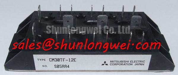
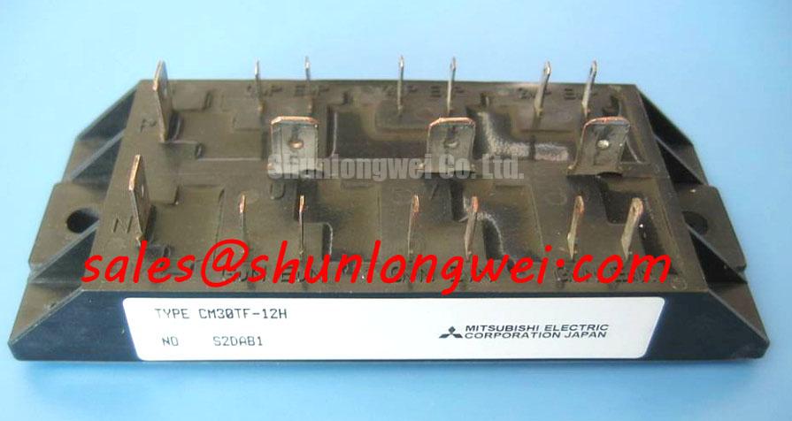
Thermal contact quality should be checked before the CM30TF-12H is exposed to operating current. The specified electrical identity is a 600.0 V, 30.0 A Mitsubishi Electric IGBT module in a module package. Those ratings establish the component category and specified electrical limits under the applicable datasheet conditions; they do not replace the thermal path assessment required for the actual inverter, servo amplifier, or motion actuator.
Remove old interface material from both the module base and heatsink without scoring the mating surfaces. A thin, continuous thermal interface layer is preferable to a thick deposit that can trap air and introduce local thermal resistance. As an Engineering Recommendation, maintenance teams may evaluate a controlled TIM thickness in the 50 to 100 μm range when the selected compound and surface finish support that process. The material supplier’s application method remains the controlling instruction.
Void elimination matters more than visual coverage alone. A bead that appears complete around the fasteners can still leave dry areas beneath the power section. Apply the compound consistently across the intended contact footprint, then lower the module vertically to avoid wiping the material toward one edge. If the baseplate or heatsink shows bowing, burrs, embedded particles, or a polished high spot, correct the mechanical condition before relying on additional compound.
Baseplate curvature compensation must follow the module’s mechanical drawing and the heatsink manufacturer’s surface requirements. Do not use screw pressure to force a visibly uneven assembly flat. Excessive local force can distort the baseplate, while insufficient contact pressure can leave an air gap that becomes more apparent after thermal cycling. The appropriate mounting fastener, washer arrangement, and tightening limit are system assembly parameters and should be taken from the applicable mechanical documentation rather than inferred from the electrical rating.
Use a diagonal or manufacturer-defined sequential tightening pattern so that pressure develops evenly across the contact area. Make an initial seating pass, inspect for movement or edge lift, and then complete the final pass using a calibrated torque tool. Record the tool identification and measured values in the maintenance log. When a module is removed, do not assume that the previous interface material can be reused; its distribution and surface condition have already changed.
Clearance around the power terminals should allow the busbar, cable lugs, insulation barriers, and inspection probe to be installed without side loading the module terminals. Keep high-current conductors short and mechanically supported. If the package includes an auxiliary emitter or separate control return, route that connection independently from the high-current emitter path where practical. A shared return path can add measurement error and gate-loop disturbance when the switching current changes rapidly.
For equipment such as a precision stepper drive or BLDC motor servo actuator, inspect the heatsink and fan path during scheduled service rather than waiting for a protective trip. Dust buildup, restricted cabinet filters, and hardened thermal compound can raise the case temperature even when the electrical load appears unchanged. Moisture deserves equal attention in cold or intermittently operated cabinets: allow condensation to clear before energization and inspect terminal insulation for tracking or contamination.
⚠️ Maintenance Note: Monitor contact temperature trends and verify the heatsink airflow path after cleaning or any change to the cabinet cooling arrangement.
Field Diagnostics & Commissioning: Pre-Installation Junction Health Check for CM30TF-12H Topologies
Cold bench screening should be performed with the module fully isolated from the discharged DC link and the gate terminals held at their respective emitter potentials to prevent accidental turn-on. Set the digital multimeter to diode-check mode and compare the readings across the main conduction paths with the documented internal topology. Where an antiparallel diode is present in the relevant path, the forward reading should be assessed for consistency between comparable channels rather than judged from an invented pass or fail threshold.
Reverse the meter leads and observe whether the measured behavior changes in the expected direction for the tested semiconductor path. An open reading where forward diode conduction is expected, an unexpected low-resistance path, or a result that differs materially from the corresponding channel warrants further investigation with the module isolated from the rest of the assembly. Contamination, parallel snubber components, connected motor cables, and driver circuitry can all affect a measurement taken in circuit.
Gate leakage checks require a controlled connection arrangement. Use the emitter or specified control return as the test reference, apply only the documented test voltage, and discharge the gate safely after testing. A basic multimeter check can reveal a gross gate-emitter short but does not verify the specified gate leakage. If the module provides a separate auxiliary emitter terminal, use that terminal for the gate loop when the manufacturer’s terminal drawing defines it as the control reference. Do not substitute the high-current emitter path without considering the voltage developed by switching current through its common inductance.
The gate driver harness should be inspected for insulation damage, loose crimp contacts, reversed polarity, and routing alongside high-current busbars. Gate-loop parasitic inductance can promote ringing when the driver output changes quickly. A practical Design Consideration is to keep the gate and return conductors closely coupled, minimize unnecessary loop area, and tune damping after observing the actual gate waveform, starting with the manufacturer-recommended gate resistance where available. The final resistor, clamp, and driver settings are determined by the switching circuit, gate charge behavior, wiring, and measured overshoot.
Do not treat a normal cold diode reading as proof that the complete switching assembly is ready for service. The driver supply, desaturation or overcurrent protection, isolation barrier, and fault-reset logic must be checked separately. Commissioning should begin with controlled low-energy conditions and instrumented observation of gate-to-emitter voltage, collector-emitter behavior, and fault response. The system engineer should verify peak voltage margins against the DC-link condition during switching tests.
High-speed semiconductor fuse coordination is part of the protection architecture. Select the fuse using its DC interruption rating, clearing behavior, and total clearing I²t, together with the fault withstand limits documented for the protected circuit. An I²t comparison alone does not establish IGBT short-circuit protection; fast driver-based shutdown must be coordinated with any published short-circuit withstand conditions. The assessment must include wiring inductance, DC-link capacitance, fault current rise, and the driver’s shutdown delay. A fuse that appears suitable from its continuous current rating may still be unsuitable for a fast semiconductor fault.
For technical background on semiconductor construction, switching behavior, and protection principles, engineers can consult The Ultimate IGBT Knowledge Base. Mitsubishi Electric’s semiconductor technology resources are also available through Mitsubishi Electric Global Semiconductor Device Technologies.
Assembly Integrity & Layout Architecture: Evaluating Thermal Capacitance Versus Heatsink Response for CM30TF-12H
Short overloads must be evaluated as transient thermal events rather than treated as steady-state current conditions. During a heavy pulse, the junction temperature responds through the semiconductor-to-case path, the case-to-interface path, and the heatsink thermal mass. A multi-RC thermal model can represent this behavior by applying the measured or specified power pulse to the thermal network and then comparing the calculated junction excursion with the applicable device limit.
This calculation is an Engineering Calculation, not an additional factory rating. Use the manufacturer’s transient thermal impedance data when available, together with the real pulse width, duty sequence, starting case temperature, and cooling condition. If the load consists of repeated acceleration and deceleration events, model the complete sequence instead of evaluating only the highest individual pulse. Thermal capacitance can delay the visible temperature rise, so a stable heatsink surface does not necessarily prove that the junction has remained within its permitted boundary.
Layout architecture directly affects both thermal and electrical stress. Keep the DC-link positive and negative paths closely coupled to reduce the commutation loop area. The same principle applies to the module terminals and capacitor bank: a large loop can increase stray inductance, allowing turn-off voltage overshoot when current changes rapidly. The design team should verify the actual collector-emitter peak with a suitable differential probe and compare it with the 600.0 V device boundary under the worst switching condition.
Busbar laminations, insulation spacing, support brackets, and terminal alignment should be inspected as one mechanical assembly. A busbar that pulls sideways on the module terminal can transmit stress into the package and loosen after thermal cycling. Avoid routing the gate harness across the power commutation loop. Where an auxiliary emitter is available, keep its return path separate from the high-current emitter connection until the intended control reference point is reached.
The gate circuit should be treated as a low-energy control loop exposed to a high-energy switching environment. Confirm the recommended gate-drive voltages, gate-voltage limits, gate charge, and switching test conditions from the applicable device documentation before selecting the driver. Gate threshold voltage is not the recommended on-state drive voltage, and the driver must supply sufficient charging and discharging current for the intended switching behavior. Gate-loop damping should be tuned from measured ringing and turn-on or turn-off behavior, with the final values determined by the complete driver and layout.
Thermal inspection after commissioning should compare equivalent operating points rather than relying on one surface temperature snapshot. Check each accessible terminal, the module case, the heatsink inlet and outlet, and the surrounding busbar insulation. A change in temperature balance between channels may indicate unequal loading, altered contact pressure, airflow obstruction, or a control timing issue. These possibilities should be separated through instrumented testing instead of assigning a single cause from the symptom alone.
When a replacement is being evaluated, compare voltage class, current class, package geometry, terminal arrangement, gate characteristics, thermal impedance, and protection compatibility as separate items. The CM200TL-12NF may be reviewed as a separate Mitsubishi Electric module for cross-model assessment, but electrical and mechanical interchangeability must be established from the target equipment documentation and the applicable device drawings.
For precision stepper and BLDC motor servo actuator systems, the final acceptance test should include the intended acceleration profile, regenerative events, cabinet temperature, cooling condition, and fault shutdown behavior. Confirm that the module is held securely after thermal cycling, that the interface material remains evenly distributed, and that the gate waveform is clean at the actual motor cable and busbar configuration used in service.